Technical2026-10-24
Irrigation pump priming problems begin on the suction side. A centrifugal pump cannot move the intended farm flow while its casing or suction line contains air. The fault may be a pump that never fills, prime that drains away after shutdown, an air leak that appears only under vacuum, or a restriction that lets the pump start but starves it at higher flow. Treat those as different failure modes before replacing parts.
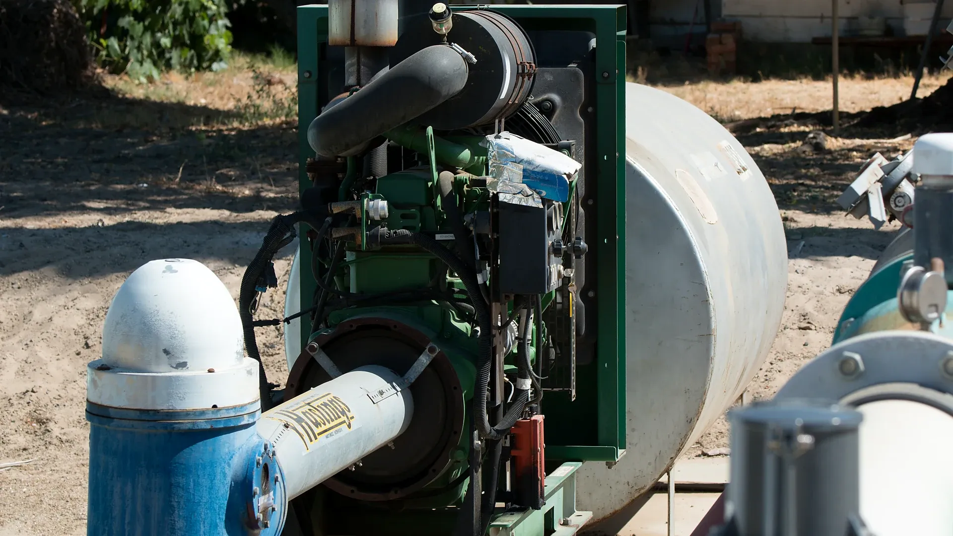
A real agricultural well pump and engine serving a micro-irrigated almond orchard. The photograph documents field pumping equipment; it does not prove that this installation has a priming fault.
This guide covers field diagnosis for surface centrifugal irrigation pumps drawing from a tank, canal, pond or shallow source. Follow the pump manufacturer's procedure and the farm's lockout, electrical and water-safety rules. Never open a casing, plug, strainer or coupling while equipment is energized or pressurized, and never keep a pump running dry to see whether it will eventually pick up water.
Start with the sequence, not a guess. Did the casing accept water before startup? Did the level at the priming port stay constant during a timed shutdown? Did the pump develop pressure for a few seconds and then lose it? Or did it hold prime yet produce less flow as the zone demand increased? Record the answer before disturbing any fitting.
To prevent loss of prime during pump shutdown intervals, technicians fit suction foot assemblies with spring-assisted PVC swing check valves that hold a full water column under static vacuum.
A pump that never draws water may still contain a large air pocket, rotate incorrectly, face excessive suction lift, or have an intake that is not submerged. A pump that works after each manual fill but is empty the next morning points toward a leaking foot valve, check valve, drain, casing gasket or above-water suction joint. A pump that holds water at rest but draws bubbles while running points toward inward air leakage, vortexing or dissolved air released by low inlet pressure.
| Observed pattern | First safe check | Likely path to investigate |
|---|---|---|
| Casing will not fill completely | Verify the approved fill and vent points | Trapped high-point air, closed valve or blocked fill passage |
| Priming-port level falls while stopped | Timed water-level retention test | Foot valve, check valve, drain, gasket or suction joint |
| Pressure rises, then collapses | Observe source level, submergence and bubbles | Vortex, intermittent air entry or source drawdown |
| Prime holds but flow stays weak | Record suction vacuum, discharge pressure and flow | Screen, foot valve, hose collapse or excessive friction |
| Repeated bubbles at stable water level | Inspect every above-water suction connection | Thread, flange, casing plug, gasket or shaft seal |
| Fault appears only at larger zones | Repeat measurements at controlled flow steps | Restriction or insufficient intake submergence at peak flow |
Stop under the approved procedure if the pump loses its water supply, fails to build stable pressure within the specified start interval, develops severe vibration or unusual mechanical noise, or shows a rapid seal or bearing temperature rise. Shut down if the intake becomes exposed, a vortex reaches the screen, a suction hose visibly flattens, or a leak creates electrical or access hazards.
Do not loosen a fitting on a running suction line to search for air. Under vacuum, the joint can pull more air inward; after shutdown, stored pressure can release water or a plug. Do not pour water into a hot pump, defeat a low-pressure trip or bypass a guard. Diagnosis must use installed instruments, safe isolation and a controlled restart.
Sketch the actual path: source, intake screen, foot valve or check valve, submerged length, flexible hose or pipe, reducers, elbows, isolation valve, priming connection, casing and pump centreline. Add the lowest operating water level, pipe inside diameter, total length and elevation of every high point. Mark all joints above the water surface because they can admit air without leaking water outward.
Suction line air ingress often occurs at loose mechanical fittings, which can be mitigated by installing continuous heavy-duty polyethylene suction piping with fusion-welded or compression-sealed joints.
The irrigation water-source assessment helps separate source yield from pump capacity. Measure the source during the irrigation set, not only before startup. A pond or well can appear full and then draw down enough to expose the intake, increase suction lift or form a vortex.
The suction line should follow the engineered arrangement and remain supported so it cannot create new high points. An upward loop can trap air that the pump cannot clear. A reducer installed in an unsuitable orientation can also create a pocket. Record the configuration before changing it so the root cause remains traceable.
After isolating energy and following the approved fill procedure, fill the casing and required suction volume completely. Open the specified vent so displaced air can leave. Mark or measure the water level at the priming port, close the system as instructed and wait for a defined interval such as 15 or 30 minutes. Use the same interval for later comparison.
A falling level is evidence that water is leaving the filled volume; it does not identify the leaking component by itself. Check the foot valve for debris or damage, a check valve for sealing direction, drain plugs for washers and torque, casing and cover gaskets for seating, and suction joints for alignment. If the water level remains stable, move to operating tests rather than repeatedly refilling.
Document the initial level, elapsed time, final level and any visible wetness. A small outside drip can matter, but the absence of a drip does not clear an above-water joint: under operation the joint is under vacuum and may pull air inward. Repair and retest using the same filled volume and timing.
Work from the source toward the casing. Check clamps, threaded adapters, flanges, unions, instrument tappings, priming plugs, casing gaskets and the shaft-seal area. Look for cracked hose ends, flattened gasket faces, crossed threads, poor pipe support and fittings carrying side load. Use only a test method approved for the materials and service; improvised flames, solvents or unsafe vacuum tests do not belong around an irrigation pump.
Observe from a protected location while the pump operates at controlled flow. Record the distance from water surface to intake, surface swirl, debris accumulation and whether an air core reaches the screen. A vortex is an intake and source-level problem, not proof of a bad pump. Correct intake geometry, submergence or approach flow through design review rather than attaching an improvised barrier.
Air can arrive with turbulent return water, a waterfall into a small tank, an exposed intake or an upstream process. Compare bubble behaviour with source level and flow. If bubbles rise only after the source draws down, inspect submergence. If they begin as vacuum rises but the source stays stable, inspect joints and hose condition. A transparent observation section may help only when it is designed, pressure-rated and safely installed for the service.
Measure stabilized flow, suction pressure or vacuum near the pump inlet, discharge pressure, source level, engine or motor speed, water temperature and active irrigation zone. The flow and pressure zoning guide explains why a larger zone changes the pump duty. Compare readings with a known-good baseline at the same zone, speed and water level.
A restriction commonly produces increasing vacuum and falling flow as demand rises. A blocked screen, partly opening foot valve, undersized pipe, excessive fittings or a flexible hose collapsing internally can all create that pattern. An air leak can cause unstable readings, visible bubbles, loss of prime or erratic discharge, but a restriction and air leak can coexist. Treat the pattern as evidence, not an automatic verdict.
Confirm gauge units, range, zero and location. A compound gauge at the inlet reports different information from a gauge several metres upstream. Calculate suction-line friction with the actual inside diameter, length, fittings and measured flow. Do not subtract a discharge-side filter loss as though it occurred before the pump.
The USDA NRCS irrigation pumping-plant guidance provides engineering context for priming, suction-line arrangement, available inlet head and troubleshooting. Apply the exact pump curve, site elevation, water temperature and project criteria; the document is not a substitute for the installation's operating instructions.
Isolate and lift the intake using the approved method. Check vegetation, silt, plastic and biological growth across the full screen area. Confirm that the foot valve opens freely and fully, closes without trapped debris, and matches the required flow orientation. A valve can seal at rest yet restrict the inlet when flow increases.
Check that the hose is rated for suction vacuum, not only positive discharge pressure. Observe its shape during the highest approved flow. Look for soft spots, delamination, a loose internal liner, sharp bends and unsupported weight at fittings. The agricultural hose inspection guide provides a broader record for hose routing and condition, but suction collapse requires the correct vacuum-rated product and installation.
Verify actual inside diameter rather than nominal label, and count valves, elbows, reducers and entrance losses. Excess length, a small bore or a partially closed isolation valve can consume inlet margin. The correction must be based on the intended flow and pump curve; replacing one elbow without recalculating the entire line may not solve the problem.
Restore the suction components, close drains, set valves to the documented starting positions and fill the casing and required suction volume. Vent air at the specified point until the procedure's completion condition is met. Verify that guards are installed and personnel are clear. Start only for the approved interval while observing pressure, flow and inlet condition.
Do not accept the repair from discharge pressure alone. A throttled valve can produce pressure while delivering too little water. Verify flow at the operating zone and compare pressure at the pump with the pressure needed downstream. The irrigation filter guide helps document filtration location and pressure loss after the pump.
| Finding | Controlled correction | Evidence required after correction |
|---|---|---|
| Water level falls during stopped retention test | Repair the verified leaking valve, plug, gasket or joint | Same timed test holds the marked level |
| Bubbles increase while source level is stable | Repair the identified above-water air path | Stable inlet reading and no persistent bubbles |
| Vortex reaches intake as level falls | Correct submergence or intake arrangement by design | No air core at minimum operating level |
| Vacuum rises and hose flattens at high flow | Install a suitable suction-rated line | Hose shape stable and flow restored at same duty |
| Screen or foot valve is obstructed | Clean safely and correct debris-management cause | Lower inlet loss and repeatable prime retention |
| Line remains restrictive after cleaning | Review diameter, length, fittings and target flow | Hydraulic check and field readings both accepted |
Change one causal item at a time when practical, then repeat the same test. If the source level, speed, zone and valve positions change, the before-and-after readings cannot isolate the repair. Keep failed parts and photographs when the cause is unclear.
Before the irrigation season, inspect the intake screen, foot valve, suction hose, supports, flange bolts, gaskets, priming plug and casing drain. Verify instrument condition and label the normal start sequence. After maintenance, perform a retention test before the first full-demand set. During the season, trend start time, inlet vacuum, discharge pressure, flow and source drawdown at a repeatable zone.
Use the drip-irrigation maintenance and monitoring plan to connect pump records with filter, zone and field observations. A gradual increase in inlet vacuum can warn of screen fouling or hose deterioration before the pump loses prime. A longer time to build pressure may reveal retained air or a leaking foot valve.
After freeze risk, seasonal shutdown or pump removal, drain and protect the equipment exactly as required for the installation. Reassembly changes gaskets and alignment, so repeat the fill, vent and retention checks. Store replacement gasket and valve information with the asset record rather than relying on appearance.
Centrifugal head is identical for all fluids, but pressure is proportional to fluid density. Air is 800 times less dense than water; an impeller producing 30 meters of head in water produces only 0.037 bar in air, completely unable to lift atmospheric water.
A standard concentric cone reducer creates a high-point pocket at the top of the pipe where rising air bubbles collect. Over hours, this air pocket grows until it enters the impeller eye, instantly breaking prime. Eccentric reducers keep the crown flat.
Apply thick shaving cream or heavy grease around every threaded joint, flange gasket, and valve stem while the pump is struggling to prime. When an air leak draws in the shaving cream, a visible depression/hole dimples into the lather.
Theoretical maximum is 10.33 meters (atmospheric pressure), but in practice static suction lift must never exceed 6.0 to 7.0 meters (20 to 22 feet) at sea level, and must be derated by roughly 1 meter for every 1,000 meters of elevation above sea level.
Products relevant to this irrigation guide.
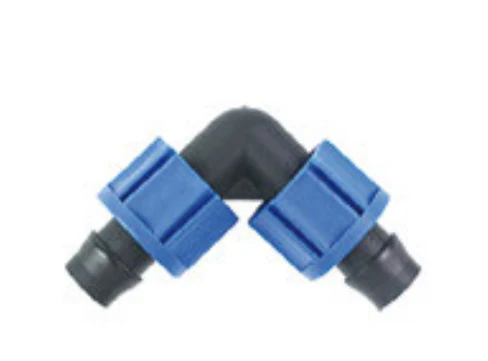
Elbow with catalogue-backed technical fields clearly documented. Compare the exact record, variant and project requirements before a technical enquiry.
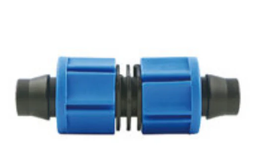
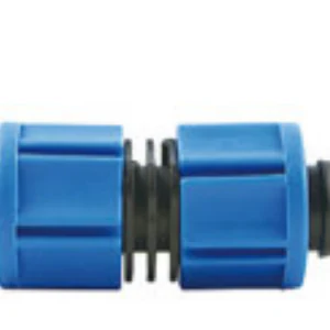
Coupling with catalogue-backed technical fields clearly documented. Compare the exact record, variant and project requirements before a technical enquiry.
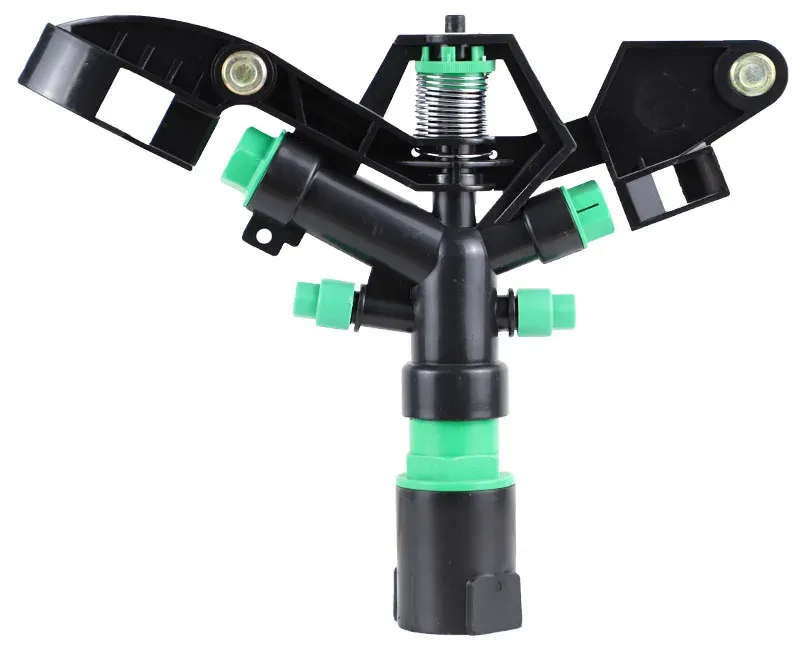
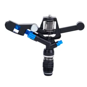
1" impact sprinkler built for agricultural irrigation, delivering long-range rotating coverage on row crops, orchards and pastures at typical field pressures.
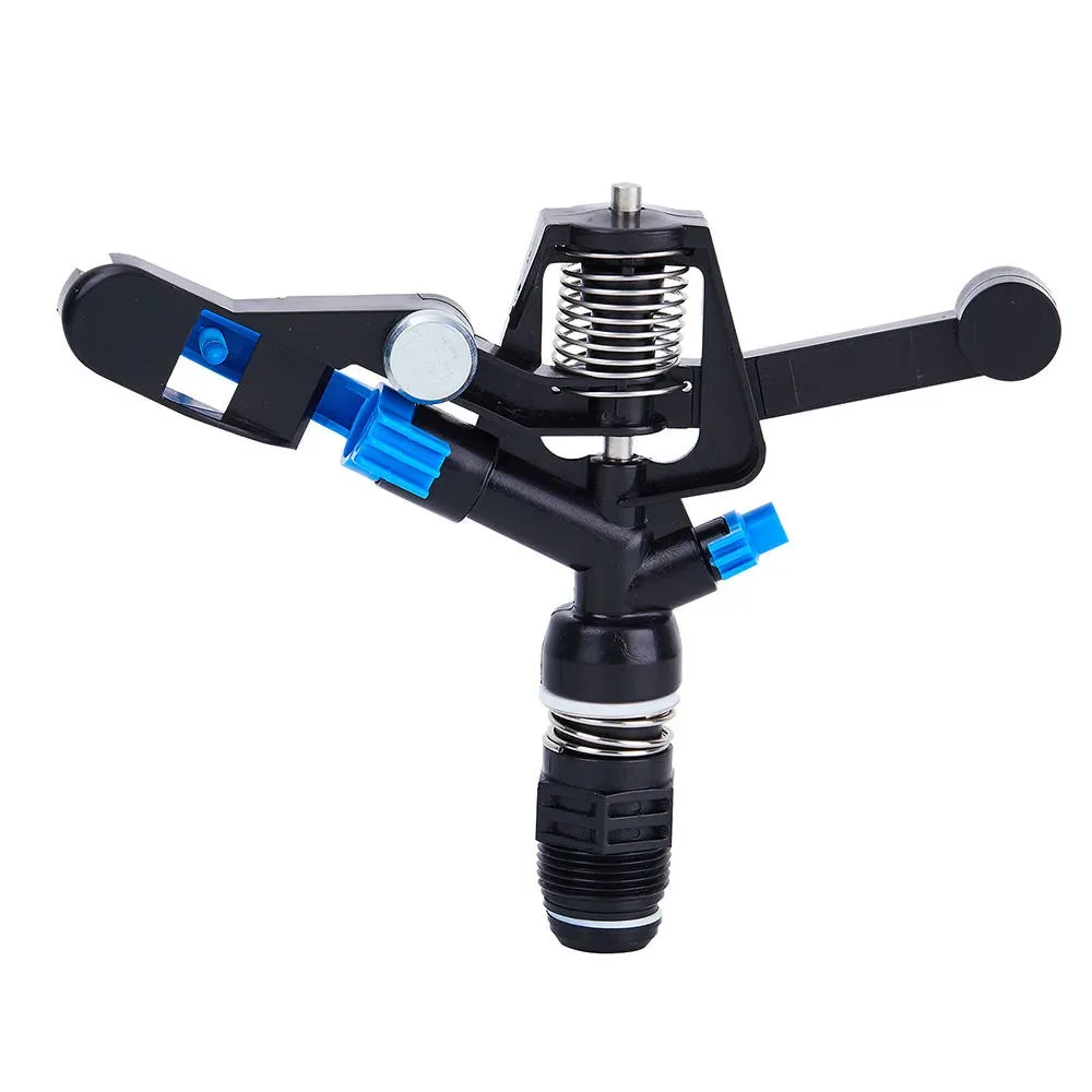
Full-circle 3/4" plastic agriculture sprinkler with a continuous 360° rotation pattern, designed for row crops, vegetable plots and pasture irrigation at standard field pressures.