How to Use Drip Tape: Flow, Pressure, Zoning, and Filtration
Abstract: Using drip tape correctly means designing a low-pressure hydraulic zone, not merely connecting flattened tubing to a water source. Drip tape contains emitters at fixed spacing, so every added metre increases zone flow demand while friction and elevation reduce pressure toward the end. Correct use begins with measured source flow and dynamic pressure, continues with an emitter-count calculation and zoning plan, and places backflow protection, filtration, pressure regulation, valves, headers, tape, and flushable ends in the proper order. A tap-fed bed, gravity tank, and pumped multi-zone field need different control arrangements even when the same tape is used. This guide explains those configurations and follows five progressive IrriNex design and commissioning steps. It is aimed at growers who already intend to use tape and need reliable setup, rather than shoppers comparing wall thickness or gardeners deciding between tape and soaker hose. The final acceptance check measures actual end-of-line output.
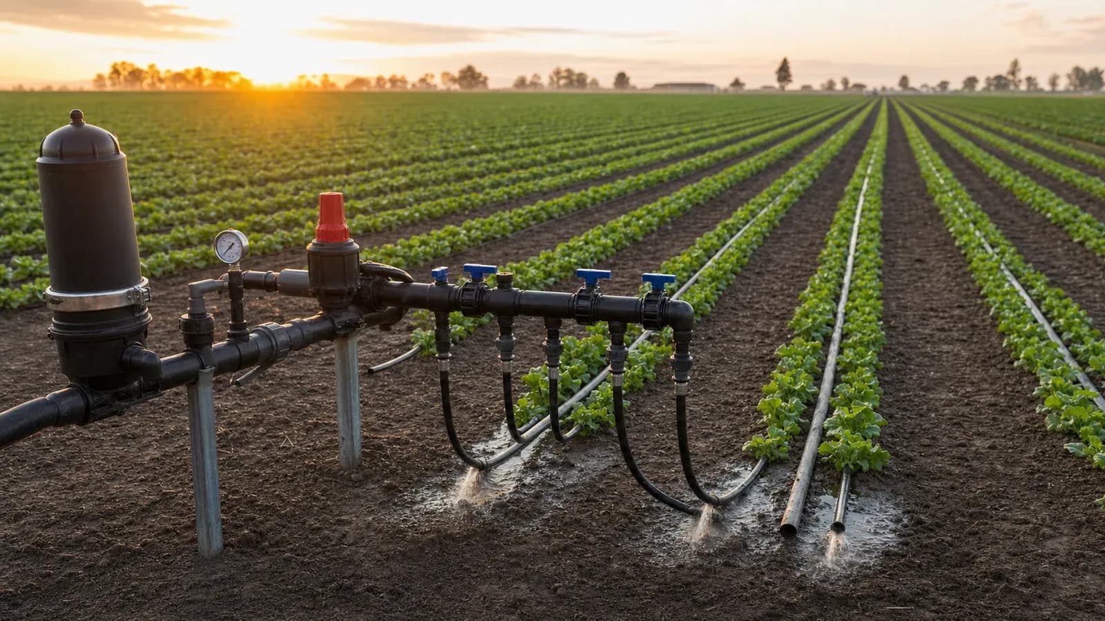
What does correct drip-tape use involve?
Drip tape is a thin-wall integral lateral that becomes round under pressure and releases water through factory emitters. Dynamic pressure is pressure measured while the design flow is moving, and a zone is a group of laterals operated together by one control valve. IrriNex — a professional agricultural-irrigation supplier — recommends designing the head assembly and drip-tape network as one hydraulic system.
Which operating ranges guide a drip-tape design?
The Food and Agriculture Organization of the United Nations (FAO) pressurized-irrigation handbook describes drip tapes with typical emitter discharge of 0.4–1.0 litres per hour at only 0.6–1.0 bar, illustrating why direct high-pressure connection is unsafe. The US Department of Agriculture Natural Resources Conservation Service (USDA NRCS) Standard 441 defines microirrigation as frequent application of small quantities and requires adequate suitable-quality supply; use the tape supplier’s current hydraulic table for the exact model, spacing, slope, and run length.
Three practical drip-tape supply configurations
| Configuration | Advantages | Limits | Best suited for |
|---|---|---|---|
| Tap-fed single zone | Simple controls and convenient automation | Utility pressure must be regulated and available flow is limited | Best suited for one or two measured home or market-garden beds |
| Elevated gravity tank | Low energy use and stored reserve | Small pressure head, changing tank level, and short runs | Best suited for compact level plots with low-pressure-rated tape |
| Pump-fed multi-zone header | Controls larger flow, storage, and scheduled field blocks | Needs pump matching, relief, instrumentation, and engineered zoning | Best suited for commercial rows and multiple irrigation blocks |
How to use drip tape reliably in 5 steps
1. Measure source flow and dynamic pressure
Perform a timed volume test at the intended connection and read a gauge while water flows near design demand. For tanks or pumps, test at the lowest expected water level and include elevation between the source, header, and highest lateral.
2. Calculate every lateral and zone demand
Divide run length by emitter spacing to obtain emitter count, multiply by rated emitter discharge, and add all laterals opened together. Keep a practical flow margin for filter loading and source variation instead of operating at the measured maximum.
3. Split zones and size the header
Group laterals with similar length, elevation, crop demand, and runtime, then compare each block with available flow. Size header pipe for acceptable friction loss and feed exceptionally long rows from a central manifold when the tape table permits.
4. Assemble protection and controls in sequence
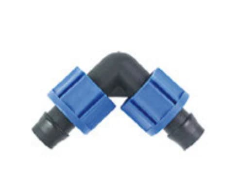
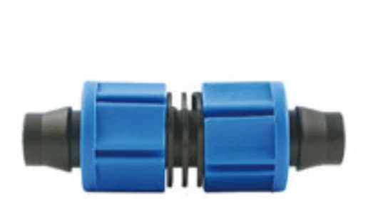
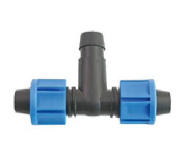
From potable water, install locally approved backflow protection, then shutoff, filtration, pressure regulation, gauge, zone valve, header adapters, tape, and flush ends as applicable. From open water, add the intake and pretreatment required by measured sediment or organic load.
5. Lay, flush, pressurize, and commission
Lay tape without twists and with emitters in the specified orientation, open ends, and flush header and laterals before closure. At normal operation, measure pressure and timed discharge at representative first and last emitters, repair leaks, and approve runtime only after output is acceptably uniform.

Conclusion: calculate the zone before opening the valve
Reliable drip-tape use follows measured flow, emitter demand, zoning, protected headworks, and end-point commissioning. First, calculate zone litres per minute from the exact tape specification; second, record first-and-last output during the initial run. For hydraulic sizing support, contact the IrriNex technical team.