Technical2026-10-29
An irrigation pump intake screen succeeds only when it stops damaging debris without taking away the suction margin the pump needs. A small or fouled screen may look protective while it raises inlet vacuum, reduces flow, encourages a vortex and moves a surface pump toward cavitation. A large screen placed on the canal bottom may bury itself in silt. The design task is therefore hydraulic as well as mechanical: define the source, calculate wetted face area, check clean and dirty loss, and make cleaning possible at the lowest operating water level.
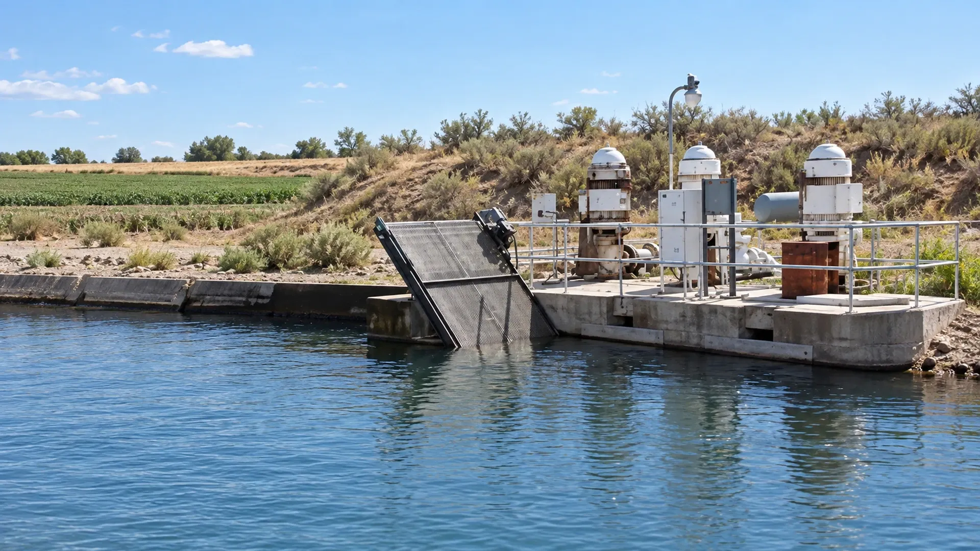
A real moving-brush slanted intake screen at an agricultural canal in Ontario, Oregon. The pump platform, screen face, brush drive and water are visible; the source photograph was retained and only the horizontal scene and clarity were adjusted.
This field worksheet is for coarse protection at an open-water pump intake. It does not specify a product, fish-protection approval, structural design or a universal cleaning interval. Local environmental permits, fish-screen criteria, canal rules and the exact pump manual can impose lower approach velocities or greater submergence. Record those requirements before buying or fabricating equipment.
A pump intake screen intercepts sticks, leaves, weeds, plastic, animals and other large material before it reaches the suction pipe or impeller. It belongs at the source end of a surface-water system. Its opening is normally much coarser than the final filtration required by drip emitters, small sprinkler nozzles or control passages. It protects the pump and makes the next treatment stage manageable; it does not produce emitter-ready water.
While coarse river intake screens exclude aquatic plants and large debris, downstream emitter protection requires dedicated secondary Y-type disc filtration units installed at the pump station header.
Keep that boundary visible on the system drawing. The irrigation filter selection guide starts with downstream water quality and emitter requirements. The drip irrigation filtration guide compares screen, disc and media filtration after the water has been lifted. Neither downstream unit should be moved casually to the suction side, where added loss directly reduces available inlet head.
Write two separate acceptance statements: “coarse material cannot enter the pump” and “delivered water meets the downstream filtration target.” Passing the first statement never proves the second. This distinction prevents an intake basket described as a screen from being mistaken for a fine filter, and it keeps fine-filter differential pressure out of the wrong part of the suction calculation.
Survey the intake while the irrigation pump is running at the largest planned zone demand. Identify floating weeds, suspended vegetation, woody debris, plastic, shells, fish and bed sediment. Note whether debris arrives steadily, in wind-driven rafts, after canal gates change or only during harvest. Record the lowest operating water level, not the quiet morning level, and measure drawdown at startup and after the source has stabilized.
Use the irrigation water-source assessment to distinguish licensed or dependable supply from instantaneous pump capacity. Maximum pump flow, minimum water level and the worst credible debris loading must appear in one row of the design sheet. A screen sized for average flow at a high water level can become partly exposed and hydraulically undersized late in the set.
| Input | Field evidence | Design use |
|---|---|---|
| Maximum simultaneous flow | Verified flow or accepted pump/system duty, with units | Numerator in the face-area calculation and basis for loss checks |
| Lowest operating water level | Staff gauge or surveyed elevation during sustained pumping | Available submerged face, suction lift and vortex check |
| Debris and sediment profile | Photos, samples, dates, wind and canal operating notes | Opening, orientation and cleaning method |
| Pump inlet condition | Suction diameter, length, fittings, elevation, vacuum or pressure | NPSHA and allowable screen loss |
| Cleaning resources | Discharge pressure/flow, power, labour, lifting access and safe platform | Passive, spray, brush or fixed-rack feasibility |
| Regulatory criteria | Permit, fish authority and canal-operator documents | Maximum approach velocity, opening and seasonal limits |
The basic screening equation is Awetted = Q / vapproach. Q is the maximum intake flow and v is the permitted velocity normal to the screen face. Use one coherent unit system: cubic feet per second divided by feet per second gives square feet; cubic metres per second divided by metres per second gives square metres. Do not enter gallons per minute directly into the equation.
To ensure intake screen approach velocities remain below 0.15 m/s and prevent vortex formation, intake headers supplying surface-mounted centrifugal irrigation pumps must provide generous submergence depth.
The USDA NRCS Irrigation Pumping Plants handbook, Appendix B identifies 0.4 ft/s (about 0.12 m/s) for active pump screens and 0.2 ft/s (about 0.06 m/s) for passive pump screens. Treat these as a documented baseline, noting that stricter local fish-screen regulations and environmental permits always govern.
Add area for partial submergence, structural blockage, debris loading and the chosen maintenance interval through explicit design factors. Do not quietly increase the allowed velocity to make a small product fit. The result is a minimum operating area at the limiting water level, not the catalogue’s total shell area.
Gross face area is the geometric outline of the screened panel or cylindrical surface. Net open area is the sum of openings after wire, perforated plate, supports and frames are removed. Actually submerged gross area is the portion below the limiting water surface and above any part blocked by the bed, bank or installation. These values answer different questions and must not share one unlabeled “area” cell.
If the applicable velocity criterion is defined across gross wetted face area, compare Q/v with the actually submerged gross face. Do not multiply by open-area percentage a second time. Use net open area with the screen maker’s clean-loss correlation, or with an accepted perforation-loss method, when that method calls for velocity through openings. Record the basis beside every calculation.
Measure the installed geometry. A 2.0 m² panel that is 60% submerged provides only 1.2 m² of gross wetted face before considering a buried lower edge or a blank frame. If its open-area ratio is 45%, its net open area within that wet face is 0.54 m². Neither 2.0 nor 0.54 m² can be substituted automatically for 1.2 m² in a gross-face approach-velocity limit.
Consider a maximum flow of 800 US gpm. This is 1.782 ft³/s, approximately 0.0505 m³/s or 181.7 m³/h. At 0.4 ft/s, an active screen needs at least 1.782 / 0.4 = 4.46 ft² of wetted face, about 0.414 m². At 0.2 ft/s, a passive screen needs at least 1.782 / 0.2 = 8.91 ft², about 0.828 m².
Using rounded SI velocities gives 0.0505 / 0.12 = 0.421 m² and 0.0505 / 0.06 = 0.842 m². Complete project calculations in one coherent unit system with unrounded limits before converting for field use.
Suppose a proposed passive assembly has 12.0 ft² gross face, but only 75% remains submerged at the lowest level and 10% is blocked by structural framing. The usable gross wet face is 12.0 × 0.75 × 0.90 = 8.10 ft²—below the 8.91 ft² minimum. The remedy requires expanding accessible wet face, adopting active cleaning, or redesigning the intake.
For an open source and a surface pump, a common screening form is NPSHA = absolute atmospheric head + static head at the pump inlet − suction-pipe friction − intake-screen head loss − water vapour-pressure head. A suction lift makes the static term negative. Use the actual reference plane, water temperature, site elevation and maximum operating flow. Compare the result with the exact pump curve’s NPSHR and the project’s required margin.
Calculate or obtain clean-screen loss at the relevant submerged area and geometry. Then evaluate a dirty condition tied to a measurable trigger. NRCS warns that actual head loss with screen geometry and debris plugging can be five to ten times a clean theoretical value. That statement is a reason to measure and allow margin; it is not permission to multiply every maker’s tested dirty-loss value again.
Example: if non-screen terms leave 1.8 m above required NPSH margin and clean screen loss is 0.10 m, an allowable dirty-screen loss of 0.60 m leaves 1.2 m. If source water drops another 0.7 m, only 0.5 m remains, failing suction margin. Always evaluate clean and dirty head loss alongside the surface-water versus groundwater comparison.
Set the screen below the lowest operating water surface with the submergence required to avoid air draw and vortices. Keep it above the bed and away from a bank pocket where silt, leaves or floating debris concentrate. The exact clearances depend on intake geometry, velocity distribution and source behaviour; copy neither a generic diameter rule nor a photograph without design review.
Route suction piping as short and direct as practical, rising continuously toward the pump. Eliminate air-trapping high points, unsupported hose, abrupt reducers, and leaking joints. Support the intake so cleaning loads and currents do not transfer stress to the pump connection.
Provide a safe retrieval path, lifting point, isolation procedure and work platform. Operators must be able to inspect both sides of the face and clear material without entering moving water or reaching near an operating brush. Protect cables and cleaning-water hoses from abrasion, sunlight and farm traffic.
| Arrangement | Best fit and evidence to obtain | Main hydraulic or maintenance risk |
|---|---|---|
| Large passive basket or panel | Low debris load; enough submerged area; easy safe retrieval | Debris mat grows unnoticed and raises suction loss |
| Rotating spray screen | Floating or fibrous material; verified pump discharge pressure and cleaning flow | Nozzle blockage or low cleaning pressure makes rotation ineffective |
| Moving-brush screen | Leaves and attached material on an accessible face; protected drive | Brush wear, jammed travel and bypass around damaged seals |
| Fixed trash rack plus intake screen | Large branches intercepted upstream with safe rake access | Rack and screen losses accumulate; material can bridge between bars |
| Duty/standby screens | Critical supply where one unit can be isolated and cleaned | Valving or flow split leaves one screen overloaded |
Compare methods at the same maximum flow and minimum water level. Include cleaning water taken from pump discharge in the water balance and operating point. A spray bar that needs pressure before the screen is clean can create a startup problem; document priming and low-pressure behaviour. A brush drive needs torque and travel checks under the heaviest expected mat.
Opening size must block material that threatens the pump while allowing acceptable loss. It is not the emitter filtration rating. The drip-tape flow, pressure and zoning guide helps define downstream zone demand and filtration load after the source screen has done its coarse work.
Install or designate repeatable measurement points for source level, suction vacuum or pressure near the pump inlet, discharge pressure and flow. Where the geometry permits, add a level or pressure observation that helps separate screen loss from source drawdown and pipe friction. A dirty-screen trigger can be stated as an allowed change from a clean baseline at the same flow and water level, plus a hard suction or NPSH limit.
Set an initial inspection interval shorter than the expected loading cycle. After several documented cycles, adjust it using the fastest observed fouling under wind, canal and seasonal conditions. Clean after safe isolation. Record removed material and damage to mesh, perforations, frame, seals, nozzles, brush, bearings and fasteners.
Do not wait for falling field pressure to identify a blocked intake. A control system may increase speed or open a valve to hide the restriction while suction margin disappears. Conversely, a higher vacuum can come from lower water level or a collapsed hose, so the trigger must be interpreted with synchronized level and flow.
Before startup, photograph the installed screen, measure gross face, open-area basis, limiting submerged face, bottom clearance and water level, and verify the accepted maximum flow. Record pump identity, speed, impeller or stage information, suction line and gauge elevations. Confirm that guards, retrieval equipment and cleaning controls work under the site procedure.
During startup and stable operation, log time, flow, suction vacuum or pressure, discharge pressure, source level, screen differential or calculated head change, cleaning pressure and cleaning flow, pump speed, vibration and noise. Observe whether a vortex reaches the screen, whether debris remains pinned, and whether the spray or brush clears the entire face. Repeat at the largest zone demand and near the lowest permitted level.
The baseline is accepted only when the hydraulic duty, face velocity, clean loss, NPSH margin, cleaning action and safe access all pass. Store the data with a photo from the same viewpoint. Future operators can then tell the difference between normal seasonal water-level change and a screen that is starving the pump.
| Observed change | Check together | Controlled response and acceptance evidence |
|---|---|---|
| Suction vacuum rises while flow falls | Water level, screen condition, speed and valve position | Isolate and clean; repeat same flow and level; vacuum returns near clean baseline |
| Visible vortex or air noise | Submergence, approach direction, source drawdown and intake position | Stop if air enters; redesign placement or operating limit; verify no vortex at limiting duty |
| Debris mat reforms rapidly | Debris source, orientation, opening and cleaning cycle | Control upstream material or revise cleaning design; document stable interval |
| Spray nozzles stop or screen rotation slows | Cleaning pressure/flow, nozzle blockage, drive and bearings | Service under isolation; verify full-face cleaning at startup and duty flow |
| Brush leaves bands of material | Brush contact, travel, wear, guide alignment and face damage | Repair adjustment or parts; inspect a complete cleaning pass |
| Flow remains low after cleaning | Suction hose, foot valve, pipe blockage, pump speed and downstream system | Test one cause at a time; accept only after flow and suction margin recover |
| Seasonal low water exposes face | Actual submerged area, bottom clearance and vortex behaviour | Reduce approved flow, reposition or enlarge intake; recalculate face area and NPSHA |
Stop according to the approved procedure if the intake becomes exposed, prime is lost, air reaches the pump, vibration changes sharply or the calculated inlet margin is breached. Never reach into a moving screen or loosen a suction connection on a running pump. Correct one cause and repeat the same controlled duty so the result remains attributable.
The final worksheet should carry the source and debris survey, maximum flow, governing approach-velocity reference, area definitions, lowest level, clean and dirty loss, NPSHA/NPSHR comparison, submergence, bottom clearance, cleaning resources and retrieval plan. Attach the commissioning log, photographs, instrument IDs, calibration or check dates, action limits and the person responsible for review.
Verify the downstream filtration stage independently. A coarse intake screen can protect the pump and still pass algae, fine silt, eggs and particles large enough to obstruct emitters. Fine screen, disc or media filtration must be selected from water analysis and outlet requirement, then monitored on the discharge side where its differential pressure belongs.
The defensible intake is not merely “large” or “self-cleaning.” It has enough verified wet face at the lowest level, acceptable loss when dirty, preserved pump suction margin, a cleaning method that works at startup and full duty, and safe access for the people who must keep it operating.
Maximum approach velocity measured 8 cm in front of the screen surface must not exceed 0.15 m/s (0.5 ft/s). This prevents aquatic life and aquatic weeds from pinning against the mesh (impingement).
$$A_{\text{total}} = \frac{Q (\text{m}^3/\text{s})}{v_{\text{approach}} (\text{m/s}) \times \%\text{Open Area}}$$ For $100\text{ L/s}$ ($0.1\text{ m}^3/\text{s}$) at $0.15\text{ m/s}$ with a $40\%$ open-area perforated drum, $A_{\text{total}} = 0.1 / (0.15 \times 0.40) = 1.67\text{ m}^2$.
A small high-pressure bypass water line from the pump discharge drives an internal water-jet wheel, rotating the stainless drum slowly while internal spray nozzles continuously blast weeds and leaves off the outer surface back into the river.
Maintain a minimum submergence depth ($S \ge 1.5 \times D_{\text{pipe}}$ or per Hydraulic Institute curves $S \ge D + \frac{v^2}{2g}$). In shallow canals, float a horizontal anti-vortex raft or wooden baffle directly over the intake to break the vortex core.
Products relevant to this irrigation guide.
IRRINEX agricultural ground cover. Diameter: 1; Length: 50m, 100m, 200m or your request. Ground cover is placed over a selected planting or landscape surface. Confirm whether the listing describes film, woven cloth or another cover before selecting dimensions and installation details.

IRRINEX irrigation valve box. Diameter: 6''; Diameter: 205mm. A valve box provides an access enclosure for an irrigation valve installation. Select dimensions and access arrangement to suit the actual valves and pipework.
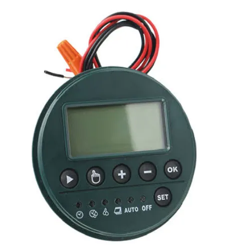
·Working voltage: DC3V.2*AA alkaline battery ·Output drive signal: 12V,100MS ·Waterproof rating:lP68
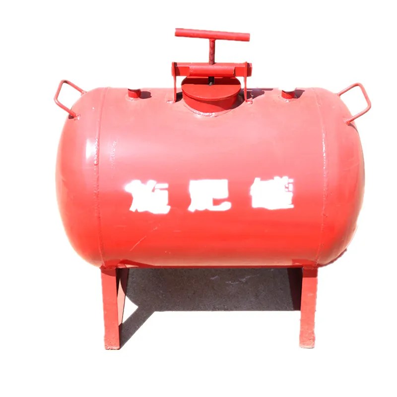
Large-capacity fertilizer tank for commercial fertigation systems with pressure bypass.