Technical2026-10-23
Irrigation pump cavitation is a pressure problem at the pump inlet, not a noise diagnosis. Crackling or gravel-like sound, vibration, unstable flow, falling pressure and pitted impeller surfaces are useful warning signs, but each has other possible causes. Confirm the actual operating flow, water level, suction losses, water temperature and the pump curve. Cavitation becomes credible when the net positive suction head available (NPSHA) is too close to, or below, the net positive suction head required (NPSHR) at that duty.
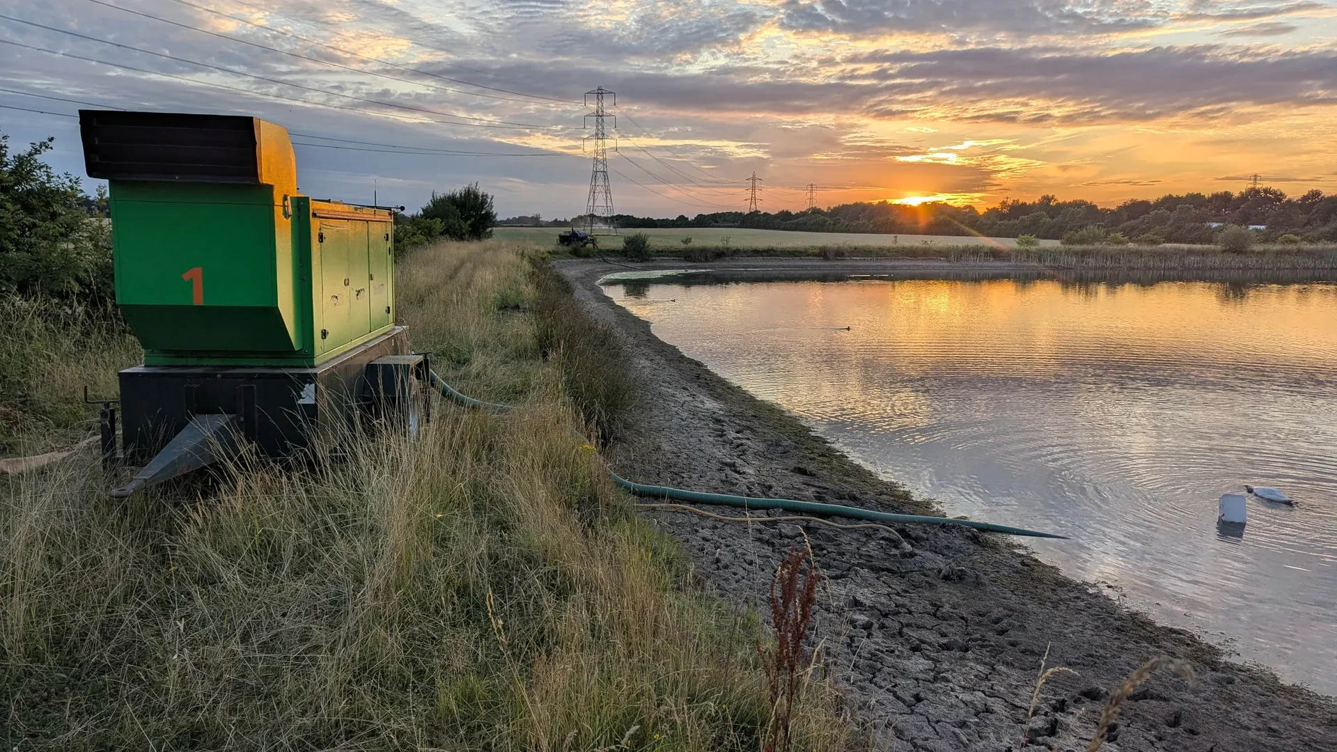
A real field irrigation pump beside a reservoir, with the suction hose running to the water. The scene illustrates the inlet path that must be inspected; it does not document a cavitation event.
This guide gives a field investigation order for surface centrifugal irrigation pumps. It does not set a universal NPSH margin or authorize work on a running pump. Isolate energy, depressurize the system and follow the pump, driver and site safety instructions before opening a casing, guard, strainer or suction connection.
Listen at the pump and from a safe distance along the suction line. Cavitation is often described as intermittent crackling that grows as flow rises. Record vibration direction and whether the discharge pressure and flow fluctuate at the same instant. Repeatable coupling between sound, vibration and hydraulic instability is stronger evidence than sound alone.
To ensure positive suction margin and eliminate cavitation damage in surface installations, operators select centrifugal surface water pumps with low net positive suction head requirements.
Do not confuse cavitation with air ingestion, worn bearings, a loose base, misalignment, debris, a damaged impeller or a control valve hunting. Air entering a leaking suction joint can produce noise and loss of prime. A bearing fault may persist when the discharge valve is closed for a brief approved test, whereas a suction-pressure problem usually changes with flow. These are clues, not universal proof.
| Observation | Record at the same time | Alternative causes to exclude |
|---|---|---|
| Gravel-like or crackling sound | Flow, inlet pressure or vacuum, discharge pressure, water level | Air leak, entrained air, debris or mechanical contact |
| Rising vibration as flow increases | Speed, valve position, vibration location and trend | Misalignment, imbalance, loose foundation or bearing wear |
| Flow or pressure falls below the baseline | Pump speed, source drawdown, filter differential and zone demand | Wrong rotation, worn impeller, blockage or changed system curve |
| Pitting on the impeller or casing | Photographs, location, hours and water chemistry | Corrosion, abrasion or prior damage |
| Repeated loss of prime | Shutdown leakage test and suction-line inspection | Foot-valve leakage, joint leak or priming failure |
Stop the pump under the approved shutdown procedure if it loses prime, runs without a stable water supply, develops severe new vibration, shows a rapid bearing-temperature rise, leaks at a hazardous rate, or produces an abnormal mechanical sound that cannot be safely distinguished. Also stop when the suction intake becomes exposed or a vortex repeatedly reaches it. Running longer to collect data can turn a correctable inlet problem into impeller, seal, bearing or motor damage.
Do not throttle or close valves blindly. A discharge adjustment can shift the operating point, but deadheading can heat the trapped water and overload equipment. Never loosen a suction fitting on a running pump to “see if air is present.” Use installed gauges, a transparent section designed for the service, controlled tests and safe isolation.
Draw the source, intake, screen, foot valve or check valve, hose or pipe, reducers, bends, isolation devices, pump centreline and gauge tapping. Measure actual inside diameter, lengths and elevation. Mark flexible sections that can collapse under vacuum and every joint above the water surface that can admit air without leaking water outward.
Minimizing suction line friction loss requires smooth-walled intake runs constructed from smooth-bore PE suction lines sized for fluid velocities below 1.5 m/s.
The irrigation water-source assessment helps separate sustainable source yield from pump capacity. A pond, canal or well can supply the design volume on average yet draw down enough during a set to reduce inlet pressure. Record the lowest expected operating water level, not the morning level before pumping starts.
For a surface pump, locate it as close to the water source and as low as practical within flood, electrical and access constraints. Use the actual suction-line design rather than a discharge-pipe rule of thumb. Shorter, larger, straighter suction piping usually reduces loss, but final size must also respect the pump and intake requirements.
Using a common open-tank convention, NPSHA can be screened as absolute atmospheric head + static head above the pump inlet − suction-pipe losses − water vapour-pressure head. A suction lift makes the static term negative. If a closed source or a different reference plane is used, follow the project equation and pump test convention consistently.
Use absolute pressure, not gauge pressure, for the pressure terms. Convert all terms to metres of the pumped liquid. Atmospheric pressure decreases with elevation, vapour pressure increases with water temperature, and friction loss rises strongly with flow. Therefore a cool-water result at low flow cannot approve the hottest, highest-flow duty.
The U.S. Department of Energy pump sourcebook explains NPSHA, NPSHR and cavitation in a pump-system context. Obtain NPSHR from the exact pump curve at actual speed, impeller diameter and flow. Do not copy it from a pump of the same nominal outlet size. Apply the margin required by the designer, owner standard or applicable engineering practice; NPSHA merely equal to published NPSHR is not a universal acceptance rule.
Assume, only for teaching, 10.1 m of atmospheric head, a 2.4 m suction lift, 1.2 m of suction losses at the measured flow and 0.3 m of vapour-pressure head. NPSHA = 10.1 − 2.4 − 1.2 − 0.3 = 6.2 m. If the exact curve gives NPSHR of 4.8 m, the numerical difference is 1.4 m. That difference must still be checked against the project’s required margin and uncertainty; it is not automatic approval.
If the water level falls another 1.0 m and a dirty screen adds 0.6 m of loss, NPSHA falls to 4.6 m. The pump may then operate below the 4.8 m curve value. This example shows why source drawdown and intake condition belong in the same record. Its figures are invented and are not a rating for any IrriNex pump.
Record stabilized flow with a suitable meter, pump speed, suction pressure or vacuum, discharge pressure, source level and water temperature. Note which irrigation zones, filters and bypasses are active. The flow and pressure zoning guide shows why a changed zone demand moves a pump to a different operating point.
Place instruments at documented locations and check their zero, range, units and recent verification. A gauge far upstream of a restrictive elbow does not report conditions at the suction flange. A dashboard flow estimate derived from motor power does not replace an independent flow observation during diagnosis.
Log the startup, stable period and shutdown. A source may look adequate for the first minute and then draw down. A foot valve can hold during operation but leak after shutdown. Time-aligned evidence distinguishes these behaviours from a constant mechanical defect.
Inspect the intake screen for vegetation, sediment and plastic; check a foot valve for incomplete opening; verify that a flexible hose keeps its shape under the highest vacuum; and compare the actual valve positions with the operating drawing. A clean-looking external surface says nothing about internal blockage. If differential pressure can be measured safely across a component, record it at more than one flow.
Trace every flange, threaded joint, gasket, primer connection and instrument tapping above the water level. An inward air leak may leave no wet mark. At the source, observe submergence, approach flow, floating debris and swirl from a safe position. A vortex or turbulent intake can entrain air even when the screen is clear. Do not improvise a submerged barrier; correct intake geometry through the responsible designer.
Follow the pump’s priming procedure and verify that the casing and required suction volume are full before start. Record whether prime is retained through an agreed shutdown interval. Repeatedly adding water treats a symptom if a foot valve, gasket or suction connection leaks. A submersible or vertical turbine installation has a different inlet arrangement, so this surface-pump checklist must be adapted.
Plot measured flow and total dynamic head on the correct pump curve. Include static lift, discharge pressure, suction pressure and relevant velocity terms under one documented convention. Confirm speed and impeller diameter. A pump far to the right of its intended range can demand more flow from the suction system and lose NPSH margin; a pump far left can face recirculation and heating risks.
Use the irrigation filter selection guide to document filtration duty without treating every pressure loss as a suction loss. A filter on the discharge side affects the system curve but is not subtracted directly in a suction-flange NPSHA calculation. Location matters.
Do not infer a pump’s health from one pressure reading. Compare with a known-good baseline at the same speed, flow, source level and valve arrangement. If the duty changed, update the system curve and operating envelope before ordering parts.
| Finding | Controlled correction | Retest evidence |
|---|---|---|
| Blocked intake screen | Isolate and clean under the approved procedure | Same flow target; lower suction loss; stable water level |
| Suction joint admits air | Repair using the specified gasket, fasteners and alignment | Prime retention and air-ingress test pass |
| Excessive suction lift after drawdown | Change intake or pump elevation through design review | NPSHA recalculated at minimum water level |
| Undersized or collapsed hose | Install a suitable suction-rated line after hydraulic review | Shape stable; measured loss within design |
| Operation beyond intended flow | Correct zone sequencing or select suitable pump/control | Duty point and required margin both accepted |
Change one causal item at a time when safe. Recreate the same source level, zone, flow target and speed, then compare suction condition, flow, pressure, sound and vibration. If several changes are made together, the record cannot show which one fixed the fault or whether margin remains.
Cleaning a screen may remove the immediate restriction but not explain why debris accumulated. Repair the source-side housekeeping, screen area or inspection interval. Replacing an impeller without restoring adequate inlet conditions invites repeat damage.
After safe isolation, inspect where damage appears. Cavitation erosion often produces localized, irregular pitting in low-pressure regions, but appearance is not conclusive. Sand abrasion tends to follow particle-laden flow paths; corrosion depends on material, water chemistry and exposure. Photograph the whole component and close views with scale, orientation and service hours.
Retain water-quality results, screen condition and removed debris. Do not call every rough surface “cavitation.” A qualified pump service specialist should interpret ambiguous damage and check clearances, balance, shaft condition and bearings before return to service.
For each event, store date, field and zone, pump identifier, speed, impeller, measured flow, suction and discharge readings, source level, water temperature, atmospheric-pressure source, estimated suction losses, calculated NPSHA, curve NPSHR and required margin. Attach gauge IDs, curve revision, photographs, audio or vibration files and the safe action taken.
Link the event to the farm hose inspection record when a temporary suction or discharge hose is used. State whether the hose is suction rated; a discharge pressure rating alone does not prove resistance to vacuum collapse.
Trend the values by operating duty. An increasing suction loss at the same flow can trigger inspection before symptoms become severe. A falling source level can trigger a different zone plan or approved shutdown. Alarm thresholds must come from the accepted equipment envelope and measurement uncertainty, not from the worked example above.
A violent, gravelly rattling sound inside the pump volute casing, sounding precisely as if the pump is pumping heavy river gravel, marbles, or broken glass, accompanied by rapid pressure gauge needle vibration.
$$NPSH_a = H_{\text{atm}} \pm H_s - h_{fs} - H_{vp}$$ where $H_{\text{atm}}$ is atmospheric pressure head, $H_s$ is static elevation lift/fall, $h_{fs}$ is suction line friction loss, and $H_{vp}$ is water vapor pressure head at operating temperature.
Agricultural engineering standards require $NPSH_a$ to exceed manufacturer $NPSH_r$ by at least 0.5 to 1.0 meter (2 to 3 feet), or a safety ratio $NPSH_a \ge 1.20 \times NPSH_r$, across all operating flow rates.
1. Lower the pump elevation closer to the water level (reducing static suction lift); 2. Enlarge the suction pipe diameter by one pipe size (reducing suction velocity to $< 1.2\text{ m/s}$ and cutting friction loss); 3. Clean or replace clogged suction foot valve strainers.
Products relevant to this irrigation guide.
Elbow with catalogue-backed technical fields clearly documented. Compare the exact record, variant and project requirements before a technical enquiry.
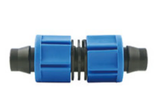
Coupling with catalogue-backed technical fields clearly documented. Compare the exact record, variant and project requirements before a technical enquiry.
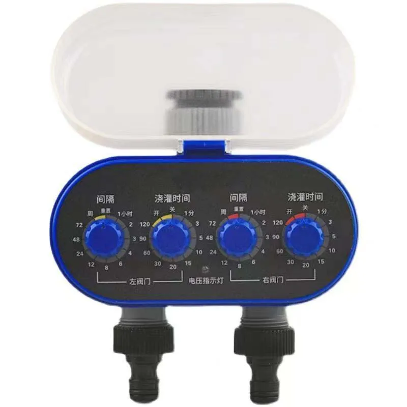
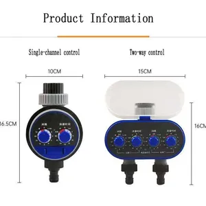
IRRINEX irrigation timer or controller. diameter: 25; SIZE: 16.5X10CM; power supply: DC 1.5V; Working water pressure: 0.02Mpa-0.8Mpa. An irrigation timer or controller provides control functions for the selected watering arrangement. Check its actual connection, power and control configuration rather than assuming every listing has the same features.
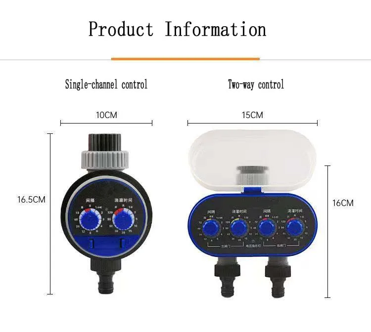
IRRINEX irrigation timer or controller. SIZE: 16.5X10CM; power supply: DC 3V; Working water pressure: 0.02Mpa-0.8Mpa. An irrigation timer or controller provides control functions for the selected watering arrangement. Check its actual connection, power and control configuration rather than assuming every listing has the same features.