Technical2026-10-20
Irrigation leak detection from flow data works only when each zone has its own stable reference. Record flow and pressure after the line has filled, compare later runs under the same valve and filter conditions, and investigate changes as a pair. A sudden flow increase with lower pressure often points toward an open break or failed fitting; lower flow with rising pressure more often suggests restriction. Flow by itself cannot tell the difference reliably.
This guide turns a flow meter into a repeatable field diagnostic. It explains how to commission a zone, calculate deviations, exclude planned events, set defensible alarms, and narrow a suspected leak before excavating or replacing parts. The objective is a traceable irrigation water management process, not a universal percentage copied from another farm.
A leak changes the hydraulic resistance of the active network. If a pipe, lateral, emitter connection, sprinkler riser, or flushing valve opens unexpectedly, the system may pass more water while holding less pressure. The pattern appears in the flow time series, but only after normal startup transients, changing pump speed, filter cleaning, and intentional configuration changes have been separated.
The minimum useful record contains the zone identity, active valve set, stabilized flow, pressure at a defined point, start and stop times, meter units, and any maintenance performed. A system-head totalizer is useful for water accounting. A meter at a block or zone boundary is more sensitive for fault isolation because a small leak represents a larger share of that meter's normal flow.
The practical rule is simple: compare like with like. Compare Zone 4 today with a healthy Zone 4 run at the same operating state. Do not compare it with the farm average or with another zone that has different emitter count, elevation, pipe length, crop stage, or pressure regulation.
A baseline is a documented envelope of healthy behavior, not one perfect number. It should describe the stabilized range expected from a particular irrigation zone under defined conditions. The center of the range may be an average or median. Its width should reflect real repeatability, meter accuracy, pressure variation, and seasonal operating changes.
Build separate baselines when the physical configuration changes. A block with two submanifolds open is a different configuration from the same block with one submanifold isolated. A drip zone after emitter replacement may need a new reference. The same applies after pump changes, pressure-regulator adjustment, major flushing, lateral extension, or a permanent change in crop rows.
| Field | Why it matters | Recording rule |
|---|---|---|
| Zone and configuration ID | Prevents unlike valve states from being mixed | Use a fixed code and list every open branch |
| Stabilized flow | Defines normal demand after filling | Record meter rate and totalizer change over a known interval |
| Reference pressure | Flow changes when pressure changes | Use the same gauge location and a suitable scale |
| Stabilization time | Excludes pipe fill, air release, and valve travel | Start the comparison only after rate and pressure settle |
| Filter state | Backwash and differential pressure affect flow | Record clean/loaded state and differential pressure if available |
| Source and pump state | Water level and speed can move the operating point | Record source, pump combination, speed, and setpoint |
| Maintenance/version date | Explains legitimate step changes | Close the old baseline and commission a new version |
If the zone is still being designed, verify its expected demand first. The drip-tape flow, pressure, zoning, and filtration guide shows why the scheduled block must fit both the source capacity and the hydraulic design. The measured baseline then tests the installed system rather than replacing design calculations.
Confirm the meter is correctly sized, installed in a full pipe where required, oriented properly, and configured with the right pulse factor or unit multiplier. Check that the displayed rate and totalizer use the units written in the log. Compare the electronic record with the local register when both are available. A meter that drops pulses, uses the wrong multiplier, or sits next to severe turbulence can create a false leak signature.
Label the pump, filter train, mainline, zone valve, submanifolds, flushing valves, pressure regulators, and any bypass. Photograph valve positions if the layout is complex. Confirm that an inline irrigation shut-off valve or manual bypass has not been left partly open. The configuration record must be detailed enough for another operator to reproduce the run.
Start the pump and open the zone using the normal sequence. Allow air valves to discharge, laterals to fill, regulators to settle, and automatic filters to complete any startup cycle. Define stabilization with data, such as flow and pressure remaining inside a narrow band for a stated period. A fixed delay alone may be insufficient when long submains or elevation changes create variable filling time.
Use multiple runs across representative operating days. One observation cannot show ordinary variability. Inspect the field during these runs so the reference is not built around a hidden break, open flush end, blocked filter, or disconnected lateral. For buried drip, compare inlet and distal pressure and walk the block where practical. The subsurface drip irrigation planning guide provides context for zones where faults are not visible at the soil surface.
Use the median stabilized flow as a robust center when occasional spikes exist. Define an initial band from observed healthy variation plus meter uncertainty, then verify it through field inspections. Avoid a tighter threshold than the measurement system can support. A threshold must be able to distinguish a hydraulic change from instrument noise.
Run a controlled filter backwash, open a flush valve briefly, change one intended submanifold, and record the signature of each event. These labeled examples become exclusion rules. They also show whether the sample interval is fast enough to capture a short burst and whether a totalizer calculation reveals events that an instantaneous display smooths away.
Have the responsible operator sign the configuration, units, healthy-run dates, accepted envelope, and alarm delay. Store the underlying readings, not only the final average. Give the baseline a version number. Recommission it after a permanent hydraulic change rather than quietly widening an alarm until it stops sounding.
For a stable comparison, calculate the percentage deviation from the reference flow:
Flow deviation (%) = (Qcurrent - Qbaseline) / Qbaseline × 100
Suppose a zone has a verified baseline of 100 m³/h at 2.0 bar. A later stabilized reading of 112 m³/h gives a +12% raw deviation. That value is meaningful only after checking that pressure, pump state, valve configuration, and filter operation match the baseline. If pressure has also fallen to 1.7 bar, the combined pattern deserves immediate field investigation. The numbers are an example, not a universal alarm threshold.
Where discharge devices behave approximately like orifices, flow may vary with the square root of pressure. A screening adjustment can be written as Qadjusted = Qmeasured × √(Preference / Pmeasured). Pressure-compensating emitters, regulators, worn nozzles, partially closed valves, and changing pump curves can violate that simple relationship. Use the adjustment to flag comparability, not to certify a leak or rewrite the manufacturer's hydraulic data.
Totalizer data provides a second calculation. Subtract the starting total from the ending total and divide by measured runtime. This average is often steadier than a noisy instantaneous rate. If the controller says a zone ran for 60 minutes but the totalized volume is inconsistent with its stabilized rate, check timestamps, pulse scaling, overlapping zones, and communication gaps before excavating.
Flow and pressure form a diagnostic pair. The same flow change can have different causes depending on the pressure direction and where the gauge is installed. The matrix below is a triage tool. It identifies the next check; it does not prove a cause remotely.
| Observed stabilized pattern | Possible causes | First field checks |
|---|---|---|
| Flow high, pressure low | Broken lateral or main, missing sprinkler, open flush valve, failed fitting, unintended second zone | Confirm valve states; isolate branches; inspect wet areas and discharge points |
| Flow low, pressure high upstream | Loaded filter, closed valve, blocked manifold, emitter clogging, collapsed line | Check filter differential pressure and valve travel; sample distal pressure and emitter discharge |
| Flow low, pressure low | Weak source, pump or well problem, suction restriction, low speed, major upstream loss | Check source level, pump state, inlet conditions, and head-control setpoint |
| Flow high, pressure near normal | Small distributed leaks, worn outlets, changed nozzle/emitter count, meter scaling error | Verify meter factor and configuration; compare branches and total volume |
| Off-cycle flow above zero | Valve not sealing, unauthorized operation, drainage through an unintended path, sensor zero error | Verify local meter/register, valve closure, bypasses, and downstream movement |
| Short spikes only | Startup filling, air release, backwash, valve travel, water hammer, sampling artifact | Match event timestamps and apply a stabilization or persistence rule |
University extension guidance for subsurface drip systems recommends establishing baseline performance and recording flow rate and operating pressure for each zone; it also describes the high-flow/low-pressure pattern associated with a likely leak. The full field guidance is available from NC State Extension.
A useful alarm system knows the operating calendar. Automatic filter backwash can create a brief change in main flow and pressure. Lateral flushing deliberately raises discharge. Fertilizer injection may use a bypass or change head loss. Frost protection, crop cooling, or a second irrigation block may be scheduled to overlap. Record these events with the same clock as the meter.
Filter condition deserves special attention. A rising differential pressure with declining zone flow indicates restriction, while a backwash can produce a temporary pulse. Use the irrigation filter selection guide to verify the filter type and capacity, then apply the maintenance procedure for that installed unit. Do not suppress an alarm simply because a filter is present; prove that the timestamp and hydraulic signature match a known cleaning event.
Seasonal changes can also be legitimate. Operators may add emitters as plants mature, close rows after harvest, replace nozzles, or change regulated pressure. Treat these as controlled configuration changes. Document the change, inspect the work, collect new healthy runs, and issue a new baseline version. Keeping the old version preserves traceability and prevents a real deterioration from being normalized away.
Begin with measurement capability. Combine meter accuracy, pulse resolution, sample interval, normal pressure movement, and observed run-to-run variability. An alert band narrower than these effects will create nuisance alarms. An excessively wide band may miss a costly leak. Use two levels when consequences justify them: a warning that requests inspection and a critical state that triggers a controlled shutdown or operator confirmation.
Add persistence. Require the deviation to remain beyond the band after stabilization for a defined number of samples or accumulated volume. Use a separate immediate rule for extreme changes that could damage equipment or flood a field. The delay must be shorter than the time needed for an unacceptable loss, yet long enough to exclude ordinary valve travel and filter cycles.
Consider absolute loss as well as percentage. A 3% deviation on a large main may waste more water than a 20% deviation on a small lateral. Estimate suspected excess flow as Qexcess = Qcurrent - Qexpected, then multiply by runtime to estimate the investigation priority. Report it as an estimate bounded by measurement uncertainty.
After repair, restore the routine in the drip irrigation maintenance and monitoring guide. A closed work order is not enough; the zone must return to its verified envelope without creating a new restriction or pressure imbalance.
A good record lets a second person reconstruct the event. Store raw samples or totals, the derived deviation, configuration version, pressure, event code, field observations, action, and verification result. Synchronize controller, gateway, meter, and operator clocks. If local time changes seasonally, store an unambiguous timestamp and display the farm's local offset.
| Record | Example entry | Decision use |
|---|---|---|
| Zone/configuration | Z04 / v3 / branches A-B-C open | Selects the correct baseline |
| Stabilized values | 112 m³/h; 1.7 bar; 10-minute window | Quantifies the paired deviation |
| Reference | 100 m³/h at 2.0 bar; accepted range recorded in v3 | Shows what “normal” means |
| Event exclusions | No backwash, flush, injection, or overlapping zone | Prevents a planned operation from being called a leak |
| Localization | Excess disappeared when branch B closed | Directs the physical inspection |
| Cause/action | Split fitting replaced; surrounding pipe inspected | Creates maintenance traceability |
| Verification | 101 m³/h at 2.0 bar after stabilization | Confirms recovery against the same baseline |
Review the log periodically. Repeated small deviations in the same branch may reveal vibration, poor support, pressure surges, animal damage, or a specification problem. Trend review converts isolated repairs into a preventive maintenance decision.
It can reveal large system-wide changes, but sensitivity falls when a small leak is a tiny fraction of total farm flow. Zone or branch measurement improves localization. Pressure observations and field inspection are still required.
No universal percentage proves one. The threshold depends on meter accuracy, hydraulic repeatability, pressure, outlet behavior, configuration, and the consequence of missed loss. Establish the healthy envelope and validate alarms through controlled field checks.
Cleaning a filter, opening a previously restricted valve, replacing clogged emitters, or restoring pump performance can legitimately increase flow. Record the work, inspect the zone, and recommission the baseline if the new configuration is permanent.
Only after a documented risk assessment. A major break may justify shutdown, while an uncertain warning during a critical crop stage may require operator confirmation and controlled isolation. Define safe fallback behavior before enabling automatic control.
Operational conclusion: irrigation leak detection becomes reliable when flow data is tied to a reproducible zone state, paired with pressure, and checked against labeled field events. Build the baseline first, preserve its version, and make every alarm lead to a specific verification step.
The controller runs each zone for 5 to 10 minutes, ignores the initial 60-second line-fill surge, and samples continuous steady-state flow rate across 3 consecutive cycles. The mathematical average is stored as the zone's nominal baseline.
Set High-Flow Warning at $+10\%$ to $+15\%$ above baseline (indicates severed lateral or missing sprinkler nozzles). Set Critical Emergency Shutdown at $+25\%$ to $+30\%$ (indicates major submain fracture), commanding immediate valve shutoff within 60 seconds.
Implement an 'Unscheduled Flow / Midnight Quiescent Audit': monitor the master flow meter during scheduled off-hours (e.g. 2:00 AM to 3:00 AM) when all zone valves are commanded closed. Any registered flow pulse confirms a leaking master valve, broken mainline, or weeping diaphragm.
Line filling dynamics: when an empty pipeline opens, water rushes in to fill pipe volume and compress air, creating an initial transient surge spike of $+50\%$ to $+100\%$ normal flow. Enforcing a 90-second debounce delay prevents false burst alarms.
Products relevant to this irrigation guide.
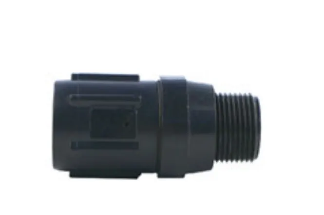
Pressure Regulator with catalogue-backed technical fields clearly documented. Compare the exact record, variant and project requirements before a technical enquiry.
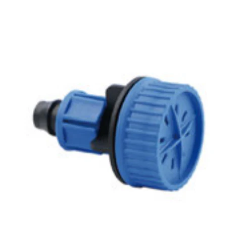
Flush Valve with catalogue-backed technical fields clearly documented. Compare the exact record, variant and project requirements before a technical enquiry.
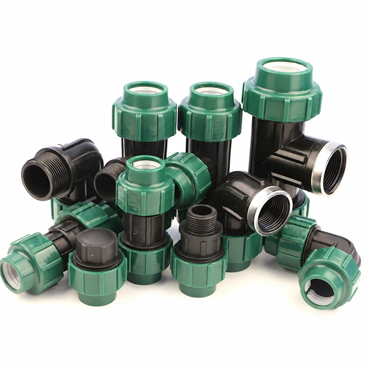
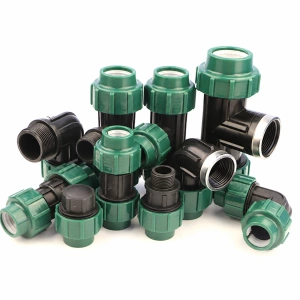
IRRINEX irrigation connection fitting. Size: 20-110mm. A connection fitting joins or terminates selected irrigation components. Choose the named fitting form and match both sides of the connection.
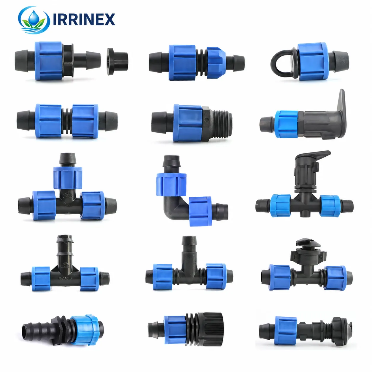
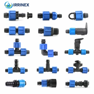
IRRINEX drip irrigation fitting. Diameter: 16mm. A drip fitting connects a selected tape, tube or lateral component. The actual fitting form and connection method should be matched to the intended line.