Technical2026-10-28
Choosing between a submersible irrigation pump and a surface irrigation pump starts with the water source, not the motor horsepower. A deep farm well, a shallow sump and an open reservoir impose different inlet conditions even when the field needs the same flow and pressure. Record static water level, stabilized pumping level, seasonal drawdown, source-to-pump elevation and service access before requesting a pump curve. Then calculate the duty point and reject arrangements that cannot stay flooded, maintain inlet margin, cool the motor or be retrieved safely.
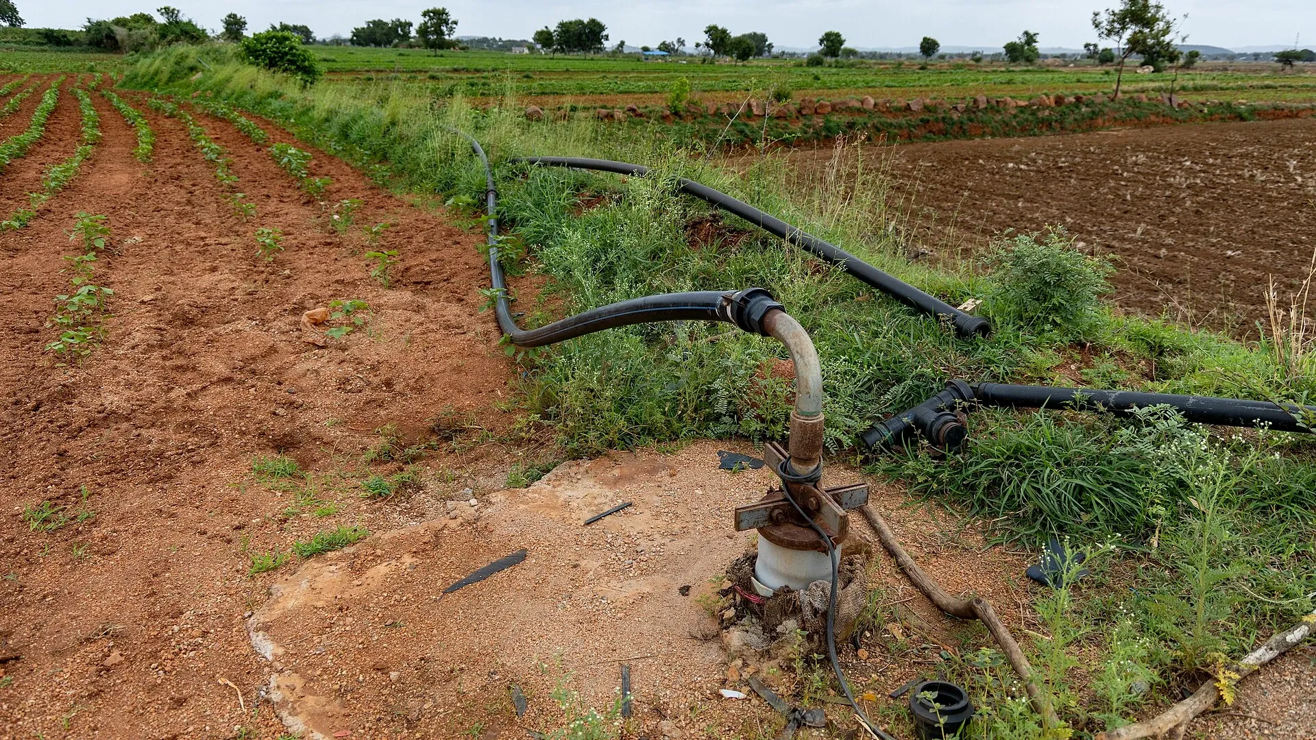
Photo: Vraj Acharya, WELL Labs, via Wikimedia Commons, CC BY-SA 4.0. The real agricultural scene shows a borewell discharge head and delivery pipes in a cotton field; the submerged pump itself is below the visible wellhead.
This guide provides a source-first selection record for agricultural irrigation. It separates pump arrangement from hydraulic principle, adds hard rejection gates before price comparison, and finishes with commissioning measurements that can be repeated after a repair. Final equipment selection, electrical protection, lifting methods and well construction require the responsible designer, pump supplier and local safety rules.
A submersible turbine pump places the pump stages and motor below the pumping water level in a well. Water moves upward through a riser pipe while the power cable descends to the motor. It avoids a long above-water suction line, but service normally means lifting the pump, riser and cable from the bore.
When pumping from shallow surface canals or storage reservoirs with limited suction lift, operators deploy solar brushless centrifugal surface pumps for ease of maintenance and direct inspection access.
A surface centrifugal pump places the pump and driver above the source. It draws water through a suction pipe from a pond, canal, reservoir or shallow sump and must be primed unless a suitable self-priming arrangement is used. Its above-ground components are accessible, yet its performance depends strongly on suction lift, inlet losses, air tightness and intake submergence.
A vertical lineshaft turbine is a third boundary case: the bowl assembly is submerged, but the motor stays at the surface and drives it through a vertical shaft. Do not label every centrifugal pump a surface pump; submersible and vertical-turbine stages also use rotodynamic principles. The practical choice concerns where the pump, motor, suction path and serviceable parts sit.
Static water level is the depth from a documented reference point to water after an agreed recovery period. Dynamic, or pumping, water level is measured while the well delivers a stated flow long enough to stabilize. Record the reference elevation, instrument, elapsed pumping time, flow and nearby well activity. The difference is drawdown, but one short test does not define the seasonal worst case.
Use records from the driest irrigation period, not only a wet-season acceptance test. Add expected long-term decline, interference from neighbouring wells and the shutdown level required to prevent dry running. For an open source, log minimum operating level, sediment, weeds, wave action, intake submergence, bank stability and flood elevation. A reservoir may have no bore depth, yet a moving shoreline can make the suction route harder than a well.
Also record water temperature, sand or grit risk, chemistry relevant to materials, bore diameter and straightness, available electrical supply, cable length, crane access and the distance to the first delivery manifold. These observations turn “well versus pond” into measurable design inputs.
Define design flow from the largest valid irrigation demand: simultaneous zones, emitter or sprinkler requirement, backwash overlap if permitted, and any minimum flow needed by control equipment. Do not size to the sum of every zone if the operating plan prevents them from running together. Document both the normal and limiting duty.
Distribution manifolds connecting surface pumps to field laterals utilize corrosion-resistant PE discharge pipelines engineered to endure cyclic hydraulic operating pressures.
Calculate total dynamic head from elevation change, required downstream pressure and friction losses at the design flow. For a well, use the stabilized pumping water level rather than ground level as the source datum. The irrigation pump sizing guide gives a consistent flow-and-TDH worksheet. Keep metres of water, kilopascals, feet and psi labelled; silent unit conversion errors can move the selected operating point far from the intended range.
Plot the duty against the exact pump curve at the proposed speed and impeller or stage configuration. Check efficiency, motor load, minimum and maximum permitted flow and the expected operating envelope as zones and water levels change. Horsepower is a result of the hydraulic duty and efficiency; it is not the first selection input.
For every surface candidate, map the intake, screen, foot or check valve, fittings, reducers, suction pipe, pump centreline and gauge point. Calculate suction static lift at the lowest source level and friction loss at maximum flow. Then assess net positive suction head available against the exact curve requirement with the project margin. Atmospheric pressure falls with site elevation and water vapour pressure rises with temperature, so a sea-level rule of thumb is not a design check.
The University of Florida IFAS irrigation-pump guidance explains centrifugal, deep-well turbine and submersible arrangements, priming and net positive suction head. Use it for principles, then apply the pump maker's curve and the project's accepted margin. A calculation that only equals the published NPSH required is not an automatic pass.
A surface arrangement also needs a repeatable priming method, a suction-rated pipe that will not collapse under vacuum, airtight joints and adequate intake submergence without vortexing. If the pump loses prime after a normal shutdown, correct the foot valve, joint or intake condition rather than making manual water filling part of routine operation.
| Candidate | Hard rejection condition | Evidence required before reconsideration |
|---|---|---|
| Surface pump | Calculated suction condition fails the required NPSH margin at minimum water level and maximum accepted flow | Revised elevation, suction route or duty with a new calculation and curve |
| Surface pump | No safe, reliable priming and prime-retention method; intake repeatedly admits air or becomes exposed | Approved intake and priming design plus shutdown retention test |
| Surface pump | Flood level, weather or public access cannot be controlled for the motor and electrical installation | Compliant elevated enclosure, drainage, guarding and electrical plan |
| Submersible pump | Bore diameter, straightness or setting depth cannot accept the pump, cable, centralizers and required cooling flow | Verified well log, gauge survey and equipment dimensional drawing |
| Submersible pump | Minimum pumping level can uncover the intake or motor cooling requirement cannot be maintained | Accepted level envelope, flow sleeve if applicable and dry-run protection |
| Submersible pump | No safe route, lifting capacity or laydown area exists for retrieving the installed string | Site-specific retrieval plan with rated lifting equipment and isolation |
| Either | No curve covers required flow and TDH across the operating envelope without overload or prohibited flow | Different pump, stages, impeller, speed control or zone plan |
A hard gate is not a weighted preference. If it fails, do not compensate with a lower purchase price or a higher motor rating. Resolve the physical constraint or remove that arrangement from the shortlist.
| Criterion | Submersible arrangement | Surface arrangement | Site evidence to record |
|---|---|---|---|
| Water-source geometry | Suited to a deep bore when submerged setting remains valid | Often practical for shallow open water with acceptable suction conditions | Static/dynamic levels, minimum open-water level, elevations |
| Priming and inlet risk | No above-water suction lift, but intake can still starve or ingest sediment | Requires airtight suction, priming, submergence and NPSH margin | Suction calculation, intake drawing, prime-retention test |
| Cooling and environment | Motor cooling depends on specified flow past the motor and water conditions | Motor needs ventilation plus protection from flood, rain, dust and heat | Cooling requirement, enclosure, flood and shade plan |
| Service access | Retrieval can require crane, crew, cable handling and long shutdown | Above-ground inspection and removal are usually easier | Lift mass, headroom, laydown route, isolation points |
| Footprint and noise | Small surface footprint and submerged motor noise | Needs pad, guards and accessible weather protection | Site plan, noise-sensitive boundaries |
| Electrical path | Long submerged cable, watertight splices and insulation testing | Shorter motor connection may be easier to inspect | Cable schedule, voltage drop, protection and test points |
| Downtime consequence | Retrieval time and specialist availability can dominate crop risk | Faster surface access may shorten diagnosis and replacement | Critical irrigation window, standby strategy, spare lead time |
Weight the surviving criteria for the farm rather than declaring one pump type universally superior. The water-source assessment helps keep sustainable yield, quality and access separate from pump capacity. A high-scoring pump cannot create water that the source cannot sustainably supply.
A well has water 18 m below the reference point after recovery and 32 m below it after two hours at 22 L/s in the dry season. The field also requires 38 m of pressure and elevation/friction allowance beyond the pumping level. A surface suction arrangement is rejected before price comparison because the physical lift is far outside a defensible suction condition. A submersible or vertical-turbine arrangement proceeds to curve, bore, cooling, cable and retrieval review.
The setting depth must remain below the accepted minimum pumping level while preserving intake clearance above sediment and any required motor-cooling path. The team checks whether the bore can pass the complete pump, riser couplings and cable guards and whether the lifting route can handle the wet string. The numbers are a teaching case, not a rating or universal setting rule.
A reservoir's minimum water surface is 1.2 m below a proposed surface-pump centreline. The intake route is short, straight and sized from measured flow, and a calculation at the hottest water condition shows the accepted inlet margin. A flood-safe pad, guarded coupling, service access, priming arrangement and submerged screened intake can make the surface option practical. A submersible intake pump may still be feasible, but retrieval, cable protection and floating debris must be compared.
If the reservoir falls, weeds load the screen or a zone change raises flow, suction loss and inlet margin change. Commission at more than one credible duty instead of approving the installation from a single mid-level test.
A submersible motor may rely on water moving past its housing at a specified minimum velocity. In a large well casing or open reservoir, a flow sleeve may be required by the equipment design; do not assume immersion alone guarantees cooling. Place level or load protection so it stops the pump before the accepted lower operating limit, and document restart delay after recovery.
A surface motor and bearings need ventilation, drainage and protection from flood, rain, solar heating, dust, animals and unauthorized contact. Weather covers must not trap hot recirculated air. Locate fuel, electrical switchgear and controls according to applicable codes and safe access. Both arrangements need protection against closed-valve operation, loss of water supply and operating points outside the accepted envelope.
Estimate the complete intervention, not only routine inspection. For a submersible system, include isolation, lifting equipment, crew, riser handling, cable and splice inspection, transport, test facilities and the time to lower and recommission the string. For a surface pump, include safe isolation, drainage, coupling alignment, lifting clearances and protection against contaminating the open source.
Use the pump-curve operating-point method to retain a known-good hydraulic baseline after service. Stock only site-critical parts supported by the maintenance plan; a spare seal does not solve a failed submerged motor, and a spare pump does not help when no crane can reach the wellhead.
Assign a downtime cost to the critical crop window: hectares missed, hours before stress becomes unacceptable, alternative water and labour needed, and supplier response time. This does not require inventing yield loss. It makes the operational consequence visible when two technically feasible options have different recovery times.
At startup, record pump identity, stage or impeller configuration, motor data, well reference point, setting depth, valve positions and active irrigation zone. Then log time, flow, suction pressure or vacuum when applicable, discharge pressure, static water level, stabilized dynamic level, speed, voltage, current, power, vibration or unusual noise and water clarity. Record the instruments, units, ranges and recent verification.
The irrigation water-meter guide helps choose an independent flow measurement for the commissioning boundary. Compare measured flow and TDH with the accepted curve, confirm motor current is within the approved range, and observe drawdown recovery and shutdown behaviour. A pressure reading without flow and water level cannot validate the selected arrangement.
Retest at the lowest and highest planned zone demands where safe. For a surface pump, verify prime retention and absence of intake vortexing. For a submersible, verify level protection, current stability and recovery restart logic. Save the accepted baseline so later deterioration can be separated from a changed source or zone.
Whenever dynamic water level drops deeper than 6.0 to 7.0 meters (20 to 22 feet) below the pump inlet. Atmospheric pressure limits surface suction lift; submersibles sit submerged at the bottom and *push* water upward with zero suction lift limits.
Accessibility: servicing a surface pump takes a standard wrench in an open shed. Servicing a failed submersible motor 100 meters down a borehole requires mobilizing a specialized crane boom truck at significant expense.
Submersible motors rely on water rushing past the motor jacket at a minimum velocity (typically $0.15\text{ m/s}$) to carry away heat. In an open lake without a tight borehole casing, water stagnates, causing motor burnout within hours unless encased in an induction sleeve.
Surface centrifugal pumps have much heavier volute casings, replaceable wear rings, and accessible impellers that can be serviced or rebuilt on-site in hours at low cost compared to replacing multi-stage submersible bowls.
Products relevant to this irrigation guide.
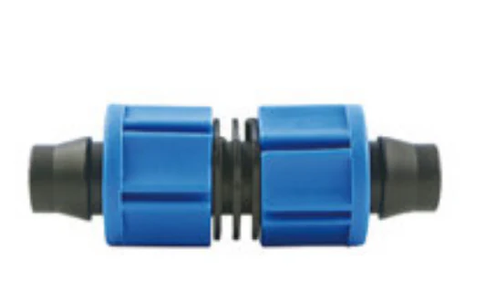
Coupling with catalogue-backed technical fields clearly documented. Compare the exact record, variant and project requirements before a technical enquiry.

IRRINEX irrigation sprinkler. Diameter: 1.0mm; Working Pressure: 2.0bar; Flow rate: 39-205L/H; Nozzle Diameter: 0.85/1.0/1.2/1.4/1.6/1.8/2.0MM. This sprinkler is a water-distribution component for a selected irrigation layout. Use the listing's named sprinkler form and exact operating data when comparing configurations.
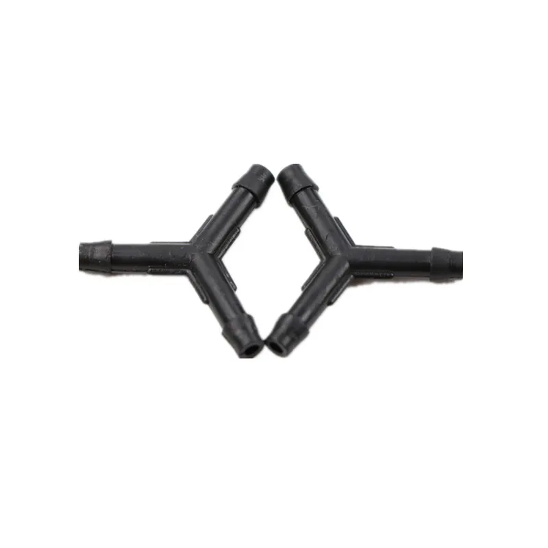
IRRINEX irrigation connection fitting. Diameter: 3mm 4mm 5mm. A connection fitting joins or terminates selected irrigation components. Choose the named fitting form and match both sides of the connection.

IRRINEX agricultural sprayer. Diameter: 1/2 in; Size: 25 mm; Flow rate: 80-220 l/h; Working pressure: 2-4.0bar. An agricultural sprayer is selected for a defined liquid-application task. Confirm the exact tank, power and nozzle configuration together with compatibility for the intended liquid.