Technical2026-10-31
Irrigation pump dry-run protection should compare independent evidence from water level, discharge pressure or flow, and motor power rather than trust one sensor. A level device can show whether water is available at the intake, a hydraulic device can show whether the pump is building and delivering water, and an electrical device can show whether the motor load has departed from its healthy pattern. Each signal also has blind spots. A defensible system uses a measured healthy baseline, a short start-up allowance, debounce, a confirmed stop, a lockout record and a supervised restart rule.
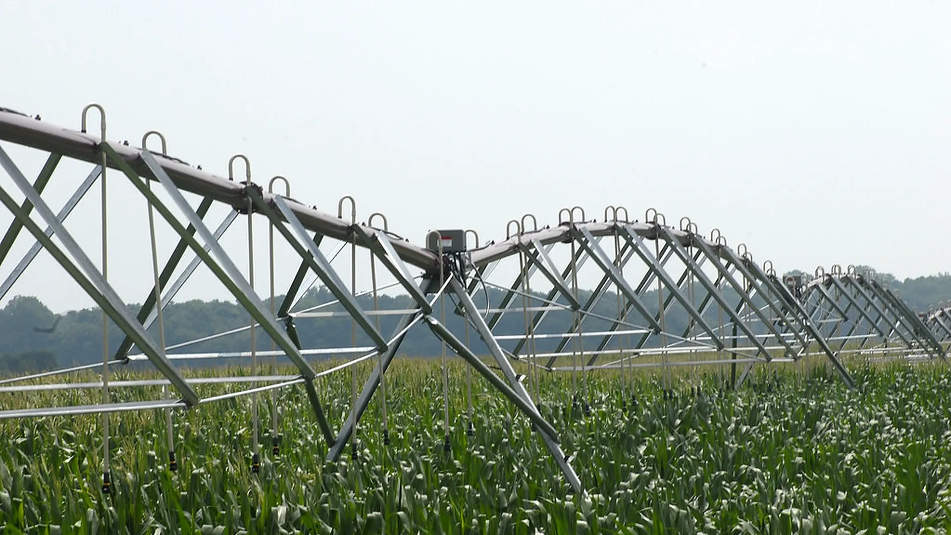
Photo: USDA NRCS / Alice Welch, public domain. The real farm scene shows a center-pivot irrigation structure and its field control enclosure. It documents agricultural irrigation equipment; it does not demonstrate a particular dry-run relay, threshold or protection result.
This guide treats dry running as a control problem that must be proved on the installed pump. It does not provide a universal pressure, current, power-factor or time threshold. The pump supplier, control-system supplier and qualified electrician must approve equipment limits, wiring, safety functions and test methods. Operators must not open or probe an energized control cabinet.
Dry running means the pump is commanded to operate without the liquid conditions needed for safe pumping and cooling. The initiating event may be a falling well or sump level, an exposed intake, loss of prime, an air leak, a blocked suction screen or an empty supply pipe. The consequence depends on pump type: loss of lubrication, seal heating, loss of motor cooling, cavitation-like noise, unstable delivery or rapid wear may occur before a remote dashboard shows a clear zero.
Integrated dry-run protection circuits safeguard brushless DC solar pumping units by sensing current drop and pressure collapse when water levels fall below intake suction bells.
Write the protected boundary first. Name the pump, source, intake elevation, normal valve lineup, expected zones, minimum source condition, prime requirement and shutdown objective. Also separate dry run from dead-head operation. A dead-headed pump may have high pressure and almost no flow, while a dry or de-primed pump may show low pressure and reduced motor load. Both can damage equipment, but they need different evidence and alarm text.
Protection must remain local enough to act when the internet is unavailable. Remote telemetry can notify and preserve context, but the decisive trip should not wait for a cloud round trip. The pump-and-valve interlock guide covers the separate condition in which no valid irrigation valve is open.
| Signal | What it can establish | Common blind spot | Useful companion |
|---|---|---|---|
| Float, probe or level transducer | Water is above or below a defined point at the measured source | Cannot prove prime, intake submergence at another location, or delivered flow; a stuck float can look healthy | Discharge flow or pressure after start |
| Discharge pressure | The pump is creating head at the gauge location | A closed valve can create pressure with no useful flow; a broken pipe can prevent pressure from rising | Flow plus valve-state evidence |
| Flow switch or flow meter | Water crosses the measured section after the line fills | Very low valid zones may sit near meter resolution; air or reverse flow can confuse some devices | Pressure and a zone-specific expected range |
| Motor current, real power or power factor | The motor load differs from its normal operating signature | Low load is not unique to dry running; voltage imbalance, speed changes and mechanical faults also alter readings | Level or hydraulic confirmation |
| VFD or motor-protection status | A drive or relay detected a configured electrical condition | A generic drive fault does not identify the hydraulic cause; settings may be wrong or bypassed | Logged pressure, flow, level and command state |
No row is a complete proof by itself. A source-level switch can stop the pump before air reaches the intake, but it cannot detect a lost prime while the source remains full. A pressure switch can detect failure to build head, but may confuse an open break with a dry intake. Power underload can react quickly, yet a variable-speed pump needs speed-aware limits. Use at least two independent physical views when the consequence of a missed trip is material.
Source → level point → intake/suction line → pump → discharge pressure point → check valve → flow meter → filter/manifold → confirmed open zone. Place the low-level device where it represents usable source water, with enough vertical separation from turbulence, sediment and the intake to avoid chatter. Put a suction-vacuum point near a surface-pump inlet when suction condition matters. Put the discharge pressure sensor close enough to the pump to observe head build-up, while documenting any check valve or closed isolation valve between sensor and field.
When dry-run alarm logic triggers, supervisory control units close rapid-acting hydraulic shutoff valves to isolate downstream mains and prevent siphon drainage.
Install the flow meter in the straight-run and orientation required by its instructions, downstream of conditions that would make the reading unstable. Obtain current, real power and power-factor values through approved protective equipment or controller data. Only a qualified electrician may install or verify electrical sensing. Do not instruct an operator to open an energized cabinet for a dry-run test.
Record sensor tag, range, unit, elevation, pipe size, calibration date, scan interval and failure state on the drawing. The irrigation pressure-sensor selection guide helps align range, accuracy and surge tolerance with the intended alarm.
Commission the pump over every permitted operating condition: low and high source levels, representative zone combinations, clean and credible dirty-filter states, normal speed range and expected supply voltage. After the line fills and values stabilize, record water level, suction condition if measured, discharge pressure, flow, speed, current, real power, power factor and time from start. Repeat enough runs to see normal variability rather than saving one ideal trace.
Define a healthy envelope by operating mode. A single undercurrent limit copied from a motor nameplate is not a dry-run setting. A small drip zone at reduced speed may draw much less power than a large pivot set while both are healthy. Likewise, a fixed pressure threshold can be valid for one zone and wrong for another. The pump-curve operating-point method helps explain why load and pressure move as zone demand changes.
Threshold documentation should state the source data, accepted scatter, sensor uncertainty, safety margin, mode selector and approver.
Pressure and flow do not appear instantly upon start command. Surface pumps require priming, long mainlines need fill time, and control valves take time to open. Establish a start-up grace period long enough for the slowest verified healthy start, yet short enough to trip before thermal equipment damage limits are exceeded.
Debounce requires a condition to persist for a defined duration or number of samples before changing state. It prevents wave action, a bouncing float or one noisy pressure sample from tripping the pump. Hysteresis uses separate trip and clear boundaries so a value near the line does not alternate rapidly. Neither device excuses a poor sensor location. Record why each delay exists and test it with real timestamps.
Do not use one blanket delay for every state. Low source level may justify an immediate inhibit before start, while “no confirmed flow” may need a measured line-fill allowance. A sensor-disconnected or out-of-range value should produce its own fail-safe action rather than be averaged into a plausible number.
A practical state machine begins in Ready. Start is allowed only when source level is valid, the required valve path is proven, safety circuits are healthy and no dry-run lockout is active. On command, enter Starting, capture a prestart snapshot and start the grace timer. Then enter Verify delivery: pressure must build and flow or another independent hydraulic signal must enter the mode-specific healthy envelope.
If verification succeeds, enter Running and continuously compare level, pressure, flow and power with their mode-aware envelopes. If the required combination fails after debounce, command Stop, confirm that the motor has stopped, close or safely position valves as designed, and enter Locked out. Record which condition caused the trip and preserve values from before and after it.
Restart should require a documented cause check. A timed restart may be appropriate for a recovering well only when the pump supplier and water-source specialist approve the cycling rule, minimum off-time and retry count. After the permitted attempts, hold a manual lockout. A continuously repeating automatic restart can turn a protective trip into repeated damage.
| Level | Pressure / flow after grace | Power signature | Interpretation to test | Control action |
|---|---|---|---|---|
| Low or invalid | Any | Any | Source unavailable or level channel failed | Inhibit start or stop; alarm with sensor state |
| Normal | No pressure build and no flow | Below healthy mode range | Loss of prime, exposed intake or severe suction restriction | Stop, lock, inspect source and prime path |
| Normal | High pressure, near-zero flow | Normal or high | Closed valve, blocked discharge or dead head | Stop under separate dead-head rule |
| Normal | Low pressure, unusually high flow | Mode dependent | Pipe break, open flush path or unintended zone | Stop or isolate according to break policy |
| Normal | Healthy pressure and flow | Low or erratic | Electrical sensing, phase, drive or mechanical issue | Controlled stop or service alarm; do not label dry run yet |
| Normal | One hydraulic sensor implausible, the other healthy | Healthy | Pressure or flow sensor fault | Apply defined degraded mode or stop; maintenance required |
The matrix is a diagnostic order, not a universal truth table. The final trip combination depends on the pump, source and consequence of failure. Use the remote irrigation alarm design method to turn each state into a message that names the affected pump, evidence and next safe check.
Assume a commissioned surface pump normally serves this zone at 280–310 kPa discharge pressure, 46–51 m³/h flow and 11.2–12.0 kW real power after stabilization. The approved start-up grace is 18 seconds and the confirmation debounce is 5 seconds. These numbers are deliberately tied to this hypothetical pump, zone and baseline; they must not be copied to another site.
| Time | State and measurements | Controller decision |
|---|---|---|
| 06:00:00 | Start request; source level valid; valve proven open; pressure 0 kPa; flow 0; power 0 | Start allowed; prestart snapshot stored |
| 06:00:04 | Motor running; 72 kPa; 3 m³/h; 8.1 kW | Within start-up grace; observe |
| 06:00:18 | Grace ends; 86 kPa; 4 m³/h; 7.6 kW | Delivery envelope not reached; start 5-second confirmation |
| 06:00:23 | 84 kPa; 3 m³/h; 7.4 kW; level still reported normal | Two hydraulic signals and low power remain abnormal; trip |
| 06:00:25 | Stop feedback confirmed; pressure decaying; flow 0 | Dry-run/prime-loss lockout; no automatic retry |
| 06:07:00 | Operator finds an unsealed priming path after safe isolation | Repair recorded; supervised prime and restart test required |
The normal level signal prevents an incorrect “empty source” diagnosis. The combined failure to build pressure and flow, plus underload relative to the same operating mode, points the investigation toward prime or suction. Review the irrigation pump priming troubleshooting guide after safe shutdown.
Create a test sheet for each permitted mode. With the pump safely available, verify sensor plausibility at rest, execute a normal start, measure time to pressure and flow, and confirm that the controller reaches Running. Then use supplier-approved simulation points to test a low-level input, loss of pressure signal, no-flow input, power-underload condition and invalid sensor value. Forced simulation should exercise the logic without intentionally running the pump dry.
Test stop feedback, lockout, alarm delivery, event timestamps, retry counter, local operation during a communication outage and restoration after the fault clears. Where the design includes a recovery delay, prove that a transient clear does not restart the pump early. Test dead-head and pipe-break branches through approved signal simulation or a controlled hydraulic method; do not create unsafe pressure or release large volumes merely to prove software.
A comprehensive pre-season commissioning inspection evaluates water source, pump, pressure gauges, flow meter, valves and field lines together, ensuring that all electrical testing and cabinet work are performed strictly by qualified personnel.
Store pump ID, zone or demand mode, start command source, controller state, trip rule, trip time, acknowledgement and reset identity. Preserve a window of raw values before and after the event: source level, pressure, flow, speed, current, voltage where available, real power, power factor, valve feedback and sensor-quality flags. Save units and scan intervals. A screenshot without raw values is weak evidence.
The alarm text should say “delivery not verified after start: low pressure + low flow + power underload” rather than simply “pump fault.” Show whether the pump stopped and whether a retry remains. Assign the next safe action: check source level externally, inspect accessible suction leaks after isolation, or dispatch qualified service. Never tell an operator to bypass the trip or reach into a live enclosure.
Trend repeated near-trips. A slowly increasing fill time can reveal a deteriorating foot valve, growing suction restriction or falling source level before a complete failure. Keep maintenance annotations on the same timeline so a changed sensor or software revision is not mistaken for a hydraulic trend.
Low water level: the level channel changes first or prevents start, while hydraulic values may still be normal until the intake margin disappears. Loss of prime: the source may remain adequate, but discharge pressure and flow fail to build and motor load can fall. Blocked suction: source level is available, suction vacuum may increase, flow declines and noise or instability may appear. Do not wait for audible damage as the primary sensor.
Closed valve or clogged discharge: pressure may rise while flow stays low, which is the opposite of many dry-run patterns. Broken pipe: flow may rise while discharge pressure falls. Worn pump: pressure and flow can deteriorate gradually while power remains plausible. Sensor failure: one channel becomes impossible, flat, out of range or inconsistent with independent instruments.
Keep “unknown” as a valid classification. When evidence conflicts, stop safely according to the approved risk rule and inspect. Do not force every trip into a dry-run category merely because that alarm already exists.
The pump supplier should confirm permitted operating envelope, maximum dry-run exposure, minimum flow, cooling requirement, restart limits and any warranty conditions. The controls supplier should document state logic, sensor failure behavior, scan timing, debounce, retained event data and bypass governance. A qualified electrician should select and test motor protection, sensing interfaces, earthing, isolation and electrical safety. The irrigation designer or operator should own source-level limits, valid zone combinations, hydraulic baselines and field response.
Review settings when the pump, impeller, drive, intake, pipe, valves, filter, flow meter, pressure sensor, level device or electrical supply changes. Repeat tests before peak season and after a material repair. A pass means the pump was allowed only under valid preconditions, healthy delivery was recognized, each injected failure caused the expected stop, the lockout was retained and the record was complete.
The strongest irrigation pump dry-run protection is a tested sequence built from independent, mode-aware evidence. Level says whether water should be available, pressure and flow say whether water was delivered, and motor power says whether the load looks credible. Their agreement supports a fast stop; their disagreement tells the technician where to investigate.
Mechanical shaft seals and internal rubber/carbon bearings rely entirely on water for lubrication and cooling. Running dry for just 45 to 90 seconds causes seal face friction temperatures to exceed 200°C, cracking silicon carbide rings and melting plastic diffuser stages.
Water creates heavy physical resistance against the spinning impeller. When the pump draws in air, load drops instantly. The relay measures the phase shift between voltage and current (Power Factor / $\cos\phi$) and real power (kW), tripping an emergency shutdown within 1 second.
Mineral scale, iron encrustation, and slime coat probe tips over time, causing electrical bridge shorts that trick the controller into believing water is present when the well is bone dry. Underpower relays are vastly more reliable because all hardware sits inside the surface control shed.
Program an automatic lockout timer of 60 to 180 minutes. This provides sufficient time for the surrounding aquifer to recharge water levels in the borehole before the pump attempts a restart.
Products relevant to this irrigation guide.
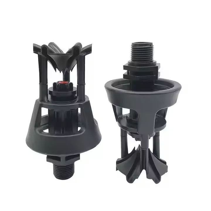
IRRINEX irrigation sprinkler. Flow rate: 254-1460L; Range: 5-6.5m; Working pressure: 1.5-4 Bar; Flow rate: 123-800L. This sprinkler is a water-distribution component for a selected irrigation layout. Use the listing's named sprinkler form and exact operating data when comparing configurations.
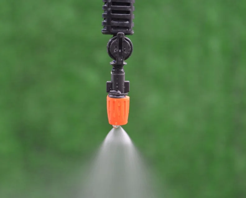
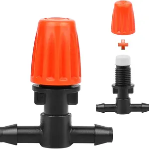
IRRINEX adjustable irrigation dripper. Working pressure: 0.5Bar~3Bar; Flow rate: 1.38L/H. An adjustable dripper is selected for a point-watering arrangement. The chosen setting should be checked under the site's actual operating conditions.

IRRINEX irrigation mist nozzle. Capacity: 1L; Power Source: Water; Nozzle: Spray; Diameter: 0.8. A mist nozzle forms a small-outlet watering component in a selected irrigation arrangement. The actual outlet, connection and operating data should guide configuration choices.
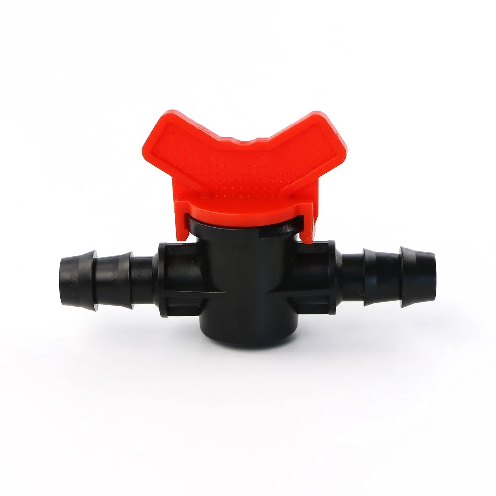
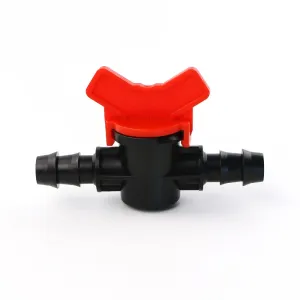
IRRINEX irrigation valve. Size: 16mm 20mm 25mm. An irrigation valve forms part of the system's flow-control arrangement. The named valve form and its actual connections should be checked before choosing a configuration.