Technical2026-10-12
An irrigation pressure sensor should be selected for the pressure it must measure, the uncertainty the decision can tolerate, and the exposure the complete installation must withstand. A larger range may cover a higher pressure while giving a larger absolute error at normal operating pressure. A high proof-pressure rating, meanwhile, does not establish accurate measurement beyond the calibrated range.
This guide develops a pressure specification, an original comparison of three fictional sensor options and a commissioning record. The examples illustrate procurement decisions for farm irrigation. They are not IrriNex product ratings, measured pipeline surges or universal operating limits.
Identify the measurement point before choosing a transducer. Pump discharge, the outlet of a IrriNex FLT-DSC-Y disc filter, a regulated zone and the end of a lateral represent different hydraulic conditions. State whether the reading supports routine monitoring, control, a filter-loss calculation or a temporary investigation of rapid events.
Specify the pressure reference. Gauge pressure is referenced to ambient atmospheric pressure; absolute pressure uses an absolute reference; differential pressure compares two pressure inputs. A number labelled bar does not establish which quantity it represents. Include that reference in the channel name, drawing and acceptance record.
The USGS guide to pressure transducers distinguishes range, reference pressure, proof pressure, resolution and response time. Its application is water-level investigation, rather than farm pipeline design. Those measurement distinctions are useful here, but its groundwater accuracy objectives are not irrigation requirements.
Connect the point to the drip irrigation pressure budget. Record the expected pressure at that location and the operating combinations that produce it. Selecting a sensor from the pump's nameplate alone leaves the pressure at the actual measuring point unresolved.
Collect the lowest and highest pressures that need valid measurement, the routine interval, and the credible exposure during startup, shutdown and abnormal operation. Identify where the evidence comes from: hydraulic design, a qualified transient assessment, previous measurements or an unresolved assumption. A maximum observed during slow logging is not automatically the maximum transient pressure.
| Condition | Evidence to request | Selection consequence |
|---|---|---|
| Routine measurement interval | Pressure at the actual tapping point across normal irrigation combinations | Accuracy and resolution must support decisions throughout that interval |
| Highest pressure requiring a valid reading | Defined event and pressure range to be measured, including uncertainty in the estimate | The required value must lie within the applicable measurement range |
| Credible positive or negative transient exposure | Qualified assessment of magnitude, duration, repetition and location | Review the sensor and connection assembly's documented exposure limits |
| Reference and environmental conditions | Gauge, absolute or differential basis; water and ambient temperature | Choose an applicable reference and performance specification |
| Process connection | Port, isolation, seals, wetted materials and any protective or damping device | Evaluate the complete pressure path and its serviceability |
Distinguish a range needed for routine control from one needed for a separate surge study. If a short transient must be quantified, the measurement system must cover its pressure and time behaviour. If routine monitoring is the purpose, the installation still needs an appropriate exposure assessment. Changing the purpose later may require different equipment.
For a regulator-related measurement, use the pressure-sustaining valve guide to clarify the relevant upstream and downstream conditions. The desired setpoint is one input. It does not describe every pressure the sensor may experience.
Read the complete performance statement, including its conditions and exclusions. A percentage may refer to span, full-scale output, reading or another defined basis. It may include selected errors at a reference temperature while excluding temperature effects, long-term drift or the receiving electronics. Ask what the figure actually covers before comparing options.
For the following example only, assume the sensor contribution at a specified reference condition is bounded by the stated percentage of pressure span. All three fictional ranges start at zero, so the span equals the upper range value. Assume the project needs valid measurement from 0 to 12 bar gauge and allows a sensor contribution no larger than ±0.06 bar at that reference condition. These are invented screening requirements, not recommended farm settings.
| Option | Measurement range | Stipulated accuracy basis | Converted bound | Screening result |
|---|---|---|---|---|
| A | 0–10 bar gauge | ±0.5% of span | ±(0.005 × 10) = ±0.05 bar | Meets the stated accuracy allowance; does not cover the required 12 bar |
| B | 0–16 bar gauge | ±0.5% of span | ±(0.005 × 16) = ±0.08 bar | Covers the required range; exceeds the ±0.06 bar allowance |
| C | 0–16 bar gauge | ±0.25% of span | ±(0.0025 × 16) = ±0.04 bar | Meets these two screening conditions; other requirements remain open |
At an illustrative operating pressure of 2 bar, these bounds correspond to 0.05 ÷ 2 × 100 = 2.5%, 0.08 ÷ 2 × 100 = 4%, and 0.04 ÷ 2 × 100 = 2% of that pressure, respectively. The original ratings are still percentages of span. Expressing the bound relative to one operating value does not change the rating basis.
Option C advances in this limited comparison; it is not approved for installation. No proof-pressure, dynamic-response, temperature, material or electrical data have been supplied. The example shows why choosing the largest range or the smallest printed percentage in isolation cannot complete the specification.
For the real system, account separately for the other relevant contributions and their uncertainty treatment. Do not assume the logger, scaling, temperature or installation add no error. A display with extra decimal places improves neither the underlying calibration nor the complete measurement uncertainty.
Proof pressure concerns a specified pressure exposure without unacceptable performance change under the stated conditions. A burst-pressure statement concerns rupture resistance under its defined test basis. Neither term should be treated as a routine measuring range or a general permission for repeated pressure excursions.
Request the applicable definitions, test conditions and restrictions for the exact model. Check whether the documentation covers the expected pulse duration, number of cycles, temperature and pressure reference. If it gives only a single number without the conditions needed for the installation, keep the exposure decision open.
Include fittings, seals, adapters, isolation devices and any connecting tube in the review. The transducer's rating cannot establish the capability of an unrated adapter. For a differential sensor, also check the allowable pressure at each port and any common-mode or one-sided exposure restrictions; a small differential reading does not mean both ports are at low pressure.
Have the hydraulic designer address pressure transients at their source and specify any suitable protection. Do not use a sensor replacement as the sole response to an unexplained overpressure event. A device that survives a surge has not necessarily captured its peak or protected the rest of the irrigation system.
A static accuracy specification describes only part of the task when pressure changes rapidly. The transducer response, pressure connection, damping, signal processing, sampling and retained data all influence the event that can be observed. A fast sensor connected to a slow or heavily averaged record can still miss the relevant change.
Research summarized by the United Kingdom's National Physical Laboratory reports different responses from combinations of transducers, instrumentation settings and mounting arrangements. The work used laboratory pressure steps; it does not prescribe a farm sampling rate. It supports evaluating the measurement assembly and settings together.
Distinguish the rate at which pressure is sampled from how often a dashboard updates or data are uploaded. A system may sample rapidly and store only an average, or upload a previously recorded peak. Record what is actually retained and how that value is calculated, rather than inferring it from the screen refresh interval.
A snubber, restrictor or long pressure connection may alter the response reaching the sensor. If such a component is needed, review its effect against the purpose of the measurement. Protection and observation must be considered together. Do not assume a smoothed trace demonstrates that the pipeline has no rapid pressure events.
Specify the exact output and receiving input: current, voltage or a documented digital interface. Confirm supply requirements, permissible load, cable arrangement, connector and signal scaling. For a current loop, verify the available voltage across the complete circuit against the selected devices' requirements. A connector that fits does not prove electrical compatibility.
Keep the sensor's pressure endpoints with the receiving channel configuration. If a replacement has a different range, update and verify the corresponding conversion deliberately. An unchanged display label can conceal an incorrect pressure calculation. Preserve fault and out-of-range indications instead of converting them into plausible normal values.
Review wetted materials and seals against the water and any chemicals that can reach the tapping point. Include cleaning or flushing conditions where relevant. Specify environmental protection for the installed connector and cable, not only the sensor body. Suitability for immersion, washdown or outdoor exposure must follow the applicable documentation.
For measurements around filtration, the filter pressure-loss guide explains why flow condition and measurement points belong with the readings. Using two pressure sensors to calculate a difference requires considering both measurements' errors; the small difference does not inherit either sensor's range specification automatically.
Agree on acceptance evidence before purchase. The reference instrument and method should suit the required pressure interval and uncertainty. Plan checks that can reveal offset, span differences and direction-dependent response where relevant. Keep the original observations and any later adjustment separate.
| Record item | Evidence to retain | Acceptance question |
|---|---|---|
| Identity and configuration | Model, serial number, range, reference, output and receiver settings | Does the installed channel match the approved specification? |
| Reference comparison | Reference identification, method, conditions and unadjusted observations | Does the complete reading meet the agreed measurement requirement? |
| Exposure and response | Applicable ratings, protective components and required dynamic evidence | Are survival and measurement requirements both addressed? |
| Control interpretation | Units, fault handling, thresholds and responsible operator | Will invalid or out-of-range data be handled explicitly? |
| Follow-up | Review basis, observed drift, service events and recalibration responsibility | What will trigger a renewed check or removal from service? |
Connect verified readings to the irrigation alarm design. Keep an equipment or data-quality fault distinguishable from a confirmed hydraulic condition. An alarm is useful when its threshold has a defensible measurement basis and its recipient knows the required response.
Review the channel after an exposure outside its documented conditions, a relevant repair or a change in range or processing. A zero check alone does not establish performance across the full required interval. Use the approved procedure to decide whether continued service, further calibration or replacement is warranted.
No. It must cover the required measurement and exposure conditions while providing suitable performance where decisions are made. With a span-based accuracy statement, widening the span can increase the absolute pressure-error bound.
No. Review measurement range and exposure ratings separately. A proof-pressure statement does not establish calibrated accuracy, useful output or suitability for repeated operation at that pressure.
No. The connection, conditioning, sampling and stored-data method must support the event being investigated. Specify and verify the complete measurement chain against that purpose.
Select a sensor where normal working pressure sits at approximately 50% to 65% of Full Scale. For a farm mainline running at 4.0 to 5.0 bar, choose a 0–10 bar (0–150 PSI) sensor. Sizing too close to peak leaves zero headroom for dynamic surges.
Proof Pressure (typically $2\times$ Full Scale) is the maximum pressure the sensor can survive without permanent zero-shift or calibration drift. Burst Pressure (typically $5\times$ Full Scale) is the catastrophic rupture point where fluid breaches the casing.
Voltage signals suffer significant voltage drop ($V = I \times R$) and electrical noise across 100+ meters of field wire. A 4–20 mA current loop delivers identical current regardless of wire resistance, and provides built-in wire-break detection (0 mA = severed wire).
A snubber is a micro-orifice fitting (sintered porous bronze or piston) installed directly between the pipe and sensor. It acts as a low-pass hydraulic filter, dampening instantaneous millisecond water hammer spikes while allowing true steady pressure to pass.
Products relevant to this irrigation guide.
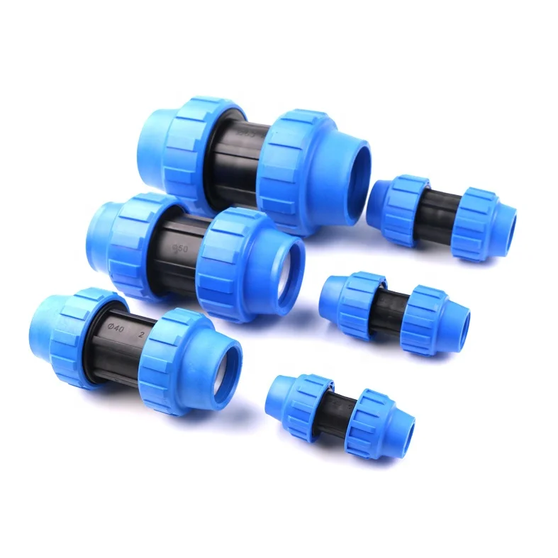
IRRINEX compression pipe fitting. Diameter: 20mm; Size: 20mm-110mm. A compression fitting joins a matched pipe to the selected connection. Check each pipe and thread dimension for the exact fitting configuration.
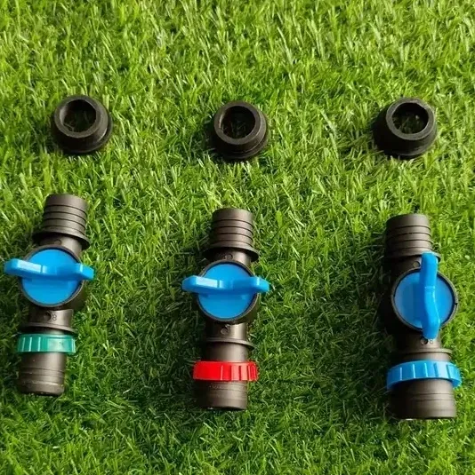
IRRINEX irrigation valve. Diameter: 25mm 28mm 32mm; size: 25mm 28mm 32mm. An irrigation valve forms part of the system's flow-control arrangement. The named valve form and its actual connections should be checked before choosing a configuration.
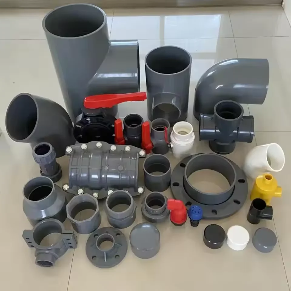
IRRINEX irrigation connection fitting. Diameter: 1. A connection fitting joins or terminates selected irrigation components. Choose the named fitting form and match both sides of the connection.

IRRINEX irrigation spray hose or tape. diameter: 16mm - 75mm; Maximum operating pressure: 200 psi; Fitting Size: 20mm-110mm; Size: 16mm - 75mm. Spray hose or tape is a distributed watering component for a selected planting layout. Use the stated dimensions and operating information for the exact configuration.