Irrigation Vacuum Protection: Prevent Pipe Collapse and Soil Ingestion
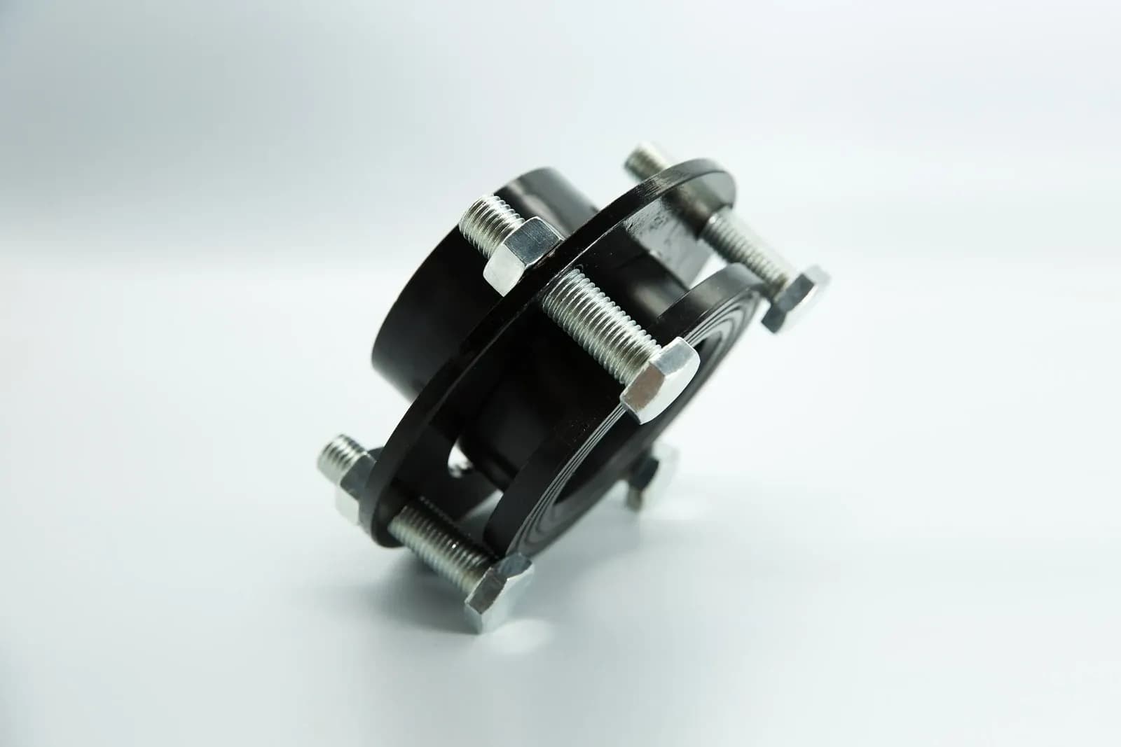
Irrigation vacuum protection requires a documented pressure limit for the pipe and a working air-entry path that can keep the affected section within that limit during the assessed event. A vent somewhere on the farm does not establish protection for an isolated branch. Protecting buried emitters from soil ingestion adds another requirement: the intake must serve the part of the network where pressure falls as water drains.
A black flanged irrigation connection assembly with silver-colored bolts. The photograph shows connection hardware, not an air valve, a collapsed pipe or evidence of a vacuum rating. Photo: IrriNex.
This guide develops a shutdown review built around external pressure, air admission and evidence from the protected section. Its original numerical examples are deliberately hypothetical. They do not rate a pipe, select a commercial air valve or demonstrate the performance of an IrriNex installation.
1. Define vacuum relative to the surroundings
In irrigation discussions, vacuum commonly means pressure below local atmosphere, not a complete absence of air or water. Distinguish absolute pressure from gauge pressure before calculating the load. If local atmospheric pressure is 100 kPa absolute and internal pressure is 96 kPa absolute, the gauge pressure is −4 kPa. The atmospheric-to-internal difference is 4 kPa.
The fluid pressure outside a pipe can exceed atmospheric pressure when the pipe is below a water surface. At a defined point on the wall, the net inward fluid-pressure difference is external absolute pressure minus internal absolute pressure at that same point. Do not compare readings taken at different elevations or times without the required corrections.
A positive internal pressure rating does not establish an allowable inward load. Wall dimensions, material behavior, temperature, initial ovality, support, burial conditions and duration all matter. The NRCS handbook on flexible conduit design, June 2005, treats vacuum, external hydrostatic pressure and structural loading separately. Its buried-pipe assessment includes buckling and deformation; an ordinary working-pressure label is insufficient evidence.
2. Build a pressure allowance before selecting the inlet
The NRCS Irrigation Pipeline standard, November 2024, limits vacuum differential to 5 psi for its air-admission design procedure. This does not mean every pipe can withstand that differential. The document covers conveyance and distribution pipelines and explicitly excludes multiple-outlet components such as microirrigation tubing. Apply the relevant project criteria and the actual component limits.
For a pressure-accounting illustration, assume an engineer has independently established an allowable net inward fluid differential of 18 kPa at a specified pipe-wall point for the exact installation and both assessed external-water cases below. Assume this limit already accounts for the pipe condition and the interaction with other structural loads. Reserve a further 3 kPa for this example's operating allowance, leaving a target maximum of 15 kPa. These invented limits are not calculated buckling strengths or generally recommended margins.
Keep local atmosphere at 100 kPa absolute and internal pressure at 96 kPa absolute. For a second case, assume the same wall point is 1.20 m below an external free-water surface open to atmosphere. With water density 1,000 kg/m³ and gravitational acceleration 9.81 m/s², the added outside hydrostatic pressure is 1,000 × 9.81 × 1.20 / 1,000 = 11.772 kPa.
| Hypothetical condition | External / internal absolute pressure | Net inward fluid differential | Comparison with the 15 kPa operating target |
|---|---|---|---|
| Outside fluid at atmosphere | 100 / 96 kPa | 4 kPa | 11 kPa below the target |
| External water head added | 111.772 / 96 kPa | 15.772 kPa | 0.772 kPa above the target |
| Internal pressure raised to the target boundary | 111.772 / 96.772 kPa | 15 kPa | At the target, without additional operating headroom |
In the wet case, the permissible atmospheric-to-internal difference at this target is only 100 − 96.772 = 3.228 kPa. The 4 kPa vacuum that fitted comfortably within the first row no longer meets the operating target. Exceeding that target is not proof of actual collapse; the table identifies an allowance problem.
This is fluid-pressure accounting, not a buried-pipe structural design. It does not replace soil-load, groundwater, traffic, buoyancy, support or buckling calculations, and the 18 kPa assumption must not be borrowed for another installation. If the governing pressure point changes as water levels change, reassess that point and the load case.
3. Follow the draining volume through each isolation state
Water can continue moving toward a lower outlet after the pump stops or a supply valve closes. Identify which sections can lose water, what replaces that volume, and whether the intended air inlet remains connected. A check valve or a closed field valve can create a separate pressure boundary even when the pipes appear continuous on a plan.
Use the air-valve placement worksheet for the surveyed profile. Add an event record rather than another generic spacing rule: which valve moved, which outlets remain available, and which section each inlet can actually serve afterward?
| State | Volume-loss route | Evidence needed for this boundary |
|---|---|---|
| Supply valve closed; lower branch still drains | Water leaves downstream of the closed valve | A supply-side air inlet cannot be credited through that closed boundary |
| Block inlet connected but its service isolation closed | The same downstream drain route remains | The installed air valve is unavailable until its approved operating connection is restored |
| Branch separated by an additional isolation | Water leaves the separated branch | Review that branch's own connected intake and pressure limit |
A drawing should distinguish deliberate operating states from accidental changes after servicing. An intake in an adjacent block cannot protect across a closed boundary. Conversely, do not assume every connected outlet is an adequate inlet: its air capacity, opening behavior and cleanliness still need assessment.
4. Check admission capacity for the defined drainage event
Assume a separate illustrative section loses 900 L over 90 seconds at a constant rate, with no replacement water entering. Its net water-volume loss is 10 L/s, or 36 m³/h. If pipe volume is fixed and internal air pressure and temperature remain approximately constant, the required incoming air volume is approximately that rate when expressed at the air conditions inside the section.
The constant-rate assumption matters. A measured total of 900 L over 90 seconds alone establishes an average; it does not establish the peak intake demand. A pressure-changing air pocket also invalidates the simple instantaneous equality. Obtain the actual drainage history or a suitable hydraulic model for the design event.
Ask for tested intake data for the exact fitted air-valve assembly at the permitted atmospheric-to-pipe pressure difference. Preserve the curve's absolute-pressure and temperature reference for its air-flow units. The example's 36 m³/h is an internal-condition volume rate, not an unqualified standard-air capacity. Convert the demand to the documented curve basis before comparing.
Include the entire path from clean atmosphere to the protected section: opening mechanism, protective inlet arrangement, service valve, riser and connections. Identify which losses a complete-assembly curve already includes. A nominal thread size, an exhaust-only curve or a valve that merely starts to open does not establish enough intake before the pipe reaches its limit.
A pump trip, line break or separating water column can require transient analysis beyond this steady replacement-volume example. Large intake capacity does not by itself establish acceptable behavior when air later exits and water columns rejoin. Retain those events as separate design cases rather than claiming the simple drainage arithmetic proves them safe.
5. Separate soil ingestion from ordinary drain-out
Oregon State University's drip irrigation introduction, updated in August 2014, identifies vacuum relief downstream of the solenoid valve as protection against soil suction into emitters at shutdown. The relevant mechanism is inward movement through a wetted emitter or opening when the internal pressure falls below the local surrounding pressure. The actual emitter design and surrounding soil-water conditions influence that pathway.
Limiting harmful suction and retaining water in every lateral are different tasks. Air admission can permit water to leave a low outlet while preventing an excessive pressure deficit higher in the connected section. Continued dripping after shutdown therefore does not prove a vacuum valve has failed. Use the drip drain-out guide for unwanted discharge at low points.
Do not assume a device advertised as anti-siphon eliminates every ingress route. Confirm the installed emitter's documented behavior, the block's admission path and whether the intake itself can become submerged or obstructed. Soil or dirty water entering through a flooded intake is a different route from material entering through an emitter. The subsurface drip irrigation guide provides the broader maintenance context.
Clogging after shutdown is not enough to identify soil ingestion. Incoming sediment, deposits, biological growth, root intrusion and damage can also affect delivery. Preserve observations and samples where appropriate; choose corrective work based on the identified mechanism rather than applying a universal chemical-cleaning recipe.
6. Record pressure where protection is needed
Agree on an approved observation sequence, measurement locations, pressure limits and stopping criteria before commissioning. Use instrumentation that can measure the expected sub-atmospheric range and event duration. A gauge that only reads positive pressure cannot demonstrate the minimum pressure, and a slow logger can miss a brief low-pressure event.
| Record item | What it must establish |
|---|---|
| Pressure boundary | Point identification, valve states, local atmosphere and gauge or absolute basis |
| Time history | Minimum pressure, duration, recording response and measurement uncertainty |
| External conditions | Water level and structural assumptions relevant to the accepted limit |
| Air path and water loss | Installed assembly, available connections and the event's drainage behavior |
Match the sensor location to the point used in the allowance. A reading near the pump does not establish pressure in an isolated high branch. Where corrections between points are necessary, document them. Interpret measured minima with uncertainty and response limits; an apparently small margin is not automatically demonstrated compliance.
Do not create an uncontrolled pipe break or abrupt shutdown to test the hypothesis. Follow the agreed commissioning procedure with competent supervision. When observed conditions differ from the model, retain the discrepancy and revise the event assessment before accepting the protection.
7. Keep the intake available without confusing water-source protection
Inspect the installed intake for blocked openings, debris, flooding, damaged internals and unauthorized caps or hoses. Verify the service isolation state and approved mounting arrangement. Before dismantling a pressure-containing part, isolate and depressurize it by the equipment's procedure; an idle pump does not establish isolation.
Pipeline vacuum relief does not establish legally compliant protection for a drinking-water source or a chemigation connection. An air valve is not a universal substitute for an approved backflow-prevention arrangement. Keep those boundaries separate using the check-valve and backflow-preventer comparison.
Revisit the record after a new drain, different pump-stop sequence, added check valve, repaired branch or changed inlet accessory. Acceptance belongs to an identified configuration and event. A previous satisfactory shutdown cannot automatically validate a new hydraulic boundary or a higher external water level.
8. Questions about irrigation vacuum protection
Does a pipe rated for high positive pressure also resist full vacuum?
Not necessarily. Obtain the permitted inward loading for the actual pipe, temperature, duration, condition and support. External water and other structural loads may leave less allowance for internal vacuum than expected.
Does an air valve prevent all water from draining out?
No. Its verified admission function limits a pressure deficit in the connected section. Retaining water at low emitters is a separate requirement and may need other documented components or operating changes.
Can one intake protect every branch after shutdown?
Only where the assessed branches retain an adequate connected air path for that state. Closed isolations, insufficient capacity or local hydraulic separation can invalidate the assumption. Verify the boundary and pressure response, not just the number of valves installed.