Technical2026-10-13
Verify irrigation meter accuracy by comparing the meter’s accumulated volume with a suitable independent reference over the same start and stop boundaries. Test more than one operating flow, calculate signed error against the reference, and retain every result in an error log. A single matching display, an unverified bucket marking, or agreement between a register and its own pulse output cannot establish accuracy.
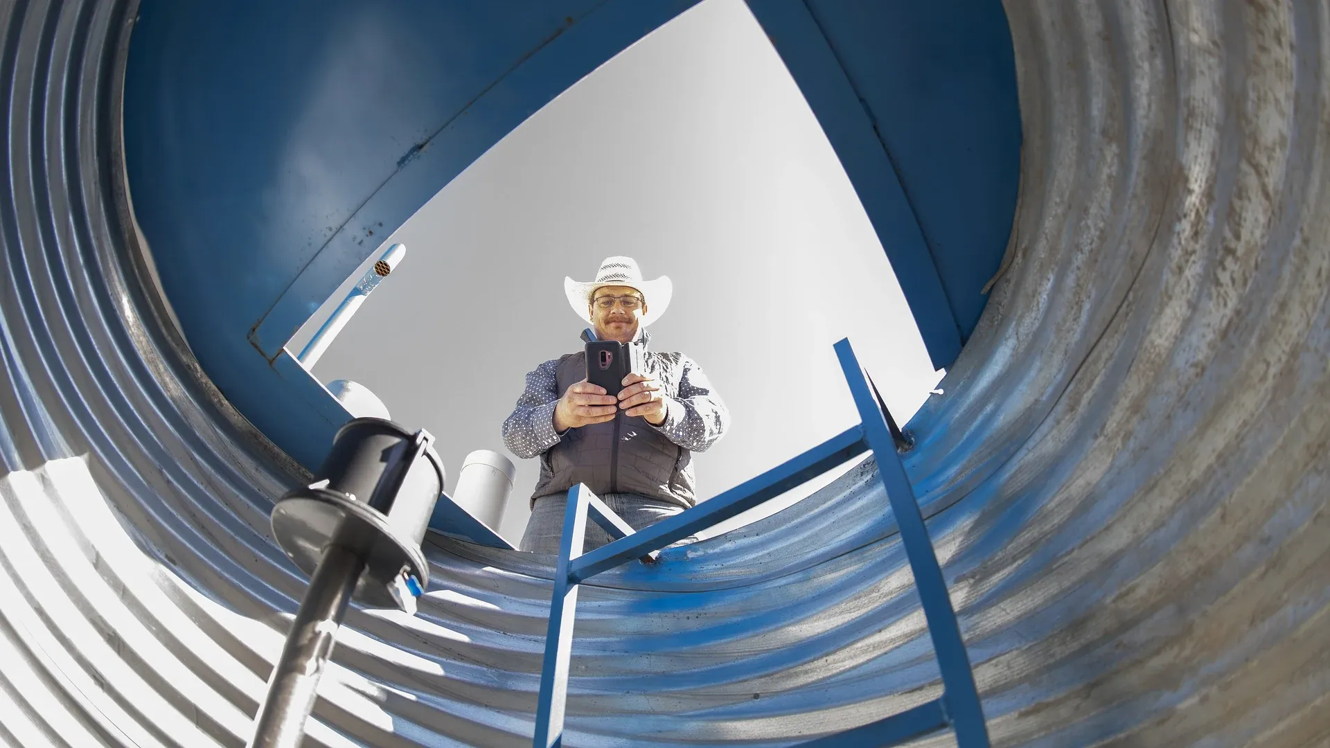
An NRCS technician photographs an irrigation-management flow meter at a Montana ranch. The real field equipment provides context; it does not show the verification procedure or support the hypothetical results below. Photo: Lance Cheung / USDA, public domain. The image was cropped and resized.
This guide creates a practical field-verification record for a closed-pipe irrigation meter. It covers a calibrated vessel where the flow is small enough to capture safely, a qualified reference meter in series, and a properly applied portable comparison instrument. It does not replace a laboratory calibration, the meter manufacturer’s procedure, a water authority’s rules, or safe isolation and discharge planning.
Start with the decision that will use the result. A seasonal water account, a IrriNex deep well submersible pump-performance check, a leak alarm and a rough operator check can require different evidence. Name the meter, location, measured boundary and intended decision. If a contract, water district or regulator controls the measurement, obtain its current acceptance method and tolerance before testing.
Use precise language. A field verification is a comparison made under recorded site conditions. It can expose a large discrepancy, drift, installation trouble or a unit mistake. Calibration normally establishes or adjusts the relationship between input and output using an adequate standard and a controlled procedure. Do not change a coefficient merely because a field comparison differs.
The US Bureau of Reclamation’s Water Measurement Manual distinguishes a discrepancy between two measurements from an error established against a comparison standard. Utah State University Extension likewise explains that meter accuracy depends on technology, installation, maintenance and operating conditions in its guide to accurate irrigation water flow measurement in pipes.
Write the pass rule before water runs. It should identify the governing source, the applicable flow range, whether the limit is percent of reading, percent of full scale or an absolute quantity, and how uncertainty is handled. When no authorized rule exists, label the exercise “diagnostic comparison” and report the discrepancy without inventing a pass threshold.
Draw a simple line diagram from the test meter to the reference. Mark every branch, bypass, drain, air IrriNex IRX-OOCV hydraulic control valve and injection point between them. During a series-meter test, all water counted by one device must pass through the other, with no unmeasured withdrawal or return. During a capture test, the vessel must receive all water counted during the interval.
Record whether the device shows instantaneous flow, cumulative volume, or both. Copy the unit and every multiplier exactly. A register marked cubic metres is different from a dial marked ×10 m³; gallons, cubic feet, acre-inches and acre-feet also cannot be interchanged. Photograph the face before and after the run so decimal positions and rollover can be reviewed.
If the comparison uses a pulse logger, first confirm the pulse value, the reciprocal form and the receiving system’s unit. The irrigation flow-meter pulse guide shows how to preserve raw counts and handle counter rollover. The pulse total is still derived from the same meter; it can check transmission and scaling, but it is not an independent accuracy reference for that meter.
Choose one clock and one volume unit for the worksheet. Convert only in clearly labelled columns and keep the raw readings unchanged. Note the time zone, because a midnight logger reset or daylight-saving change can otherwise look like lost volume.
The reference must cover the flow, water and installation conditions with uncertainty small enough for the decision. “Recently purchased” and “digital” are not evidence of reference quality. Record its identity, range, calibration or verification status, resolution and relevant setup requirements.
| Reference approach | Useful application | Evidence and main limitation |
|---|---|---|
| Verified volumetric vessel or tank | Small discharge that can be captured completely and safely | Current vessel volume, wetting/draining method, readable level and proof that no water escapes; a nominal bucket size is only a screening estimate |
| Qualified master meter in series | Pipe flows too large to capture | Applicable certificate or test record, suitable range, correct installation and no branch or leak between meters |
| Portable clamp-on or insertion instrument | Temporary comparison where the pipe and access permit | Independent suitability, pipe geometry, full-pipe condition, mounting record and uncertainty; portability alone does not make it a standard |
| Authorized delivery or test facility measurement | Regulated accounts or higher-consequence acceptance | Written method, synchronized boundary and responsibility agreed with the authority or qualified laboratory |
For a vessel test, verify usable volume rather than trusting a moulded “capacity” label. Define whether the endpoint is a gauge mark, overflow level, mass-derived volume or another calibrated indication. Wet and drain the vessel consistently, control splashing and residual water, and use a captured volume large enough that reading resolution is not a dominant fraction of the result.
For a portable ultrasonic comparison, record pipe outside diameter, wall thickness, liner, material, transducer spacing, coupling, mounting position and signal-quality indicators. The ultrasonic flow-meter installation guide provides a field record for that setup. Two devices exposed to the same distorted velocity profile may agree and still share a bias.
Inspect the meter against its exact installation instructions. Check orientation, full-pipe condition, upstream disturbances, required straight lengths, grounding where applicable, deposits, debris, air pockets, damaged cables, unreadable registers and unexpected bypass positions. Do not apply one generic straight-pipe rule to every model.
Record the water source and visible condition. Fibrous material can obstruct a rotor; deposits can change a wetted section; entrained air can disturb several measurement principles. If water quality may explain a pattern, retain observations or samples using the irrigation water-testing guide. Do not diagnose the meter from colour or turbidity alone.
Operate valves and the pump until the test condition is stable. Write down active zones, pump speed, pressure near the meter, filter state and any cycling equipment. A changing filter differential can change real flow without changing meter accuracy; the filter pressure-loss guide helps separate that hydraulic change from an instrument discrepancy.
Plan safe discharge, access and communication. Only qualified personnel should isolate, open or alter a pressurized line. A bucket method that requires someone to hold a container in an unsafe jet is not an acceptable reference method. Stop the test if hoses move, a vessel can overflow, an electrical enclosure is exposed or the system leaves its allowed pressure range.
Use totalized volume for the primary comparison when both systems provide it. Instantaneous displays can update and damp at different rates, so two screens photographed at the same second may not represent the same averaging interval. If only flow rate is available, define a synchronized averaging period and preserve the underlying samples.
At each condition, make at least enough repetitions to detect inconsistent operation; the governing procedure may specify the exact count. Do not average away an unexplained outlier. Mark splashing, valve movement, air release, register hesitation, logger gaps and reference resets as events, then decide whether the affected run is invalid under a rule written before reviewing the outcome.
Add a zero-flow observation when the installation allows it. Confirm the totalizer remains unchanged over a recorded interval and check for a known bypass or reverse flow. A zero display does not prove a closed valve, and a changing totalizer may represent actual leakage, reverse flow handling, electrical noise or meter trouble. Investigate before assigning a cause.
For each run, calculate the test-meter volume as Vind = final indicated total − initial indicated total, after applying the documented register multiplier. Calculate the reference volume, Vref, independently. Then use:
Signed error (% of reference reading) = 100 × (Vind − Vref) ÷ Vref
A positive result means the test meter indicated high relative to the reference; a negative result means it indicated low. Keep the sign. Absolute error can summarize magnitude, but it cannot show whether the farm’s recorded volume is systematically high or low.
| Flow condition | Reference volume Vref | Indicated volume Vind | Difference | Signed error |
|---|---|---|---|---|
| Low | 2.00 m³ | 2.12 m³ | +0.12 m³ | 100 × 0.12 ÷ 2.00 = +6.0% |
| Normal | 10.00 m³ | 10.20 m³ | +0.20 m³ | 100 × 0.20 ÷ 10.00 = +2.0% |
| High | 20.00 m³ | 20.20 m³ | +0.20 m³ | 100 × 0.20 ÷ 20.00 = +1.0% |
These invented results show why one normal-flow point is insufficient. The same 0.20 m³ difference represents 2% at 10 m³ but 1% at 20 m³. The low-flow result is worse even though its absolute difference is smaller. No row is a universal pass or fail; apply only the documented criterion and reference uncertainty for the actual use.
Never divide by the indicated value while labelling the answer “percent of reference.” If the totalizer rolls over, reconstruct the delta from its documented maximum and retain both photographs. If units differ, convert the two volumes to the same unit before subtracting, and show the conversion factor.
An accuracy statement is incomplete without its denominator and range. Suppose a flowmeter with a stated full scale of 100 m³/h indicates 21 m³/h while the reference indicates 20 m³/h. The difference is 1 m³/h. Expressed against the reference reading, the error is 100 × 1 ÷ 20 = +5%. Expressed against the stated full scale, it is 100 × 1 ÷ 100 = +1% of full scale.
Both calculations can be arithmetically correct, but they communicate very different low-flow performance. Copy the exact definition from the applicable specification, and do not convert “±1% full scale” into “±1% of every reading.”
| Statement element | Question to record | Why it matters |
|---|---|---|
| Denominator | Reading, reference, full scale, span or absolute quantity? | Changes the permitted difference, especially at low flow |
| Applicable range | Which minimum and maximum flows qualify? | A headline value may not apply outside the tested interval |
| Conditions | Which water, temperature and installation assumptions apply? | Field conditions can differ from a laboratory statement |
| Uncertainty and confidence | What does the reference certificate or method state? | A close result may be inconclusive near the acceptance boundary |
| Combined terms | Is there an added zero, pulse, resolution or fixed-error term? | One percentage may not describe the complete specification |
Plot signed error against flow and compare repetitions. A consistent positive bias across the range raises a different question from a low-flow error that improves as flow increases. Scattered results point first toward unstable flow, reading resolution, poor synchronization, intermittent debris or an unsuitable reference. One pattern does not prove one cause.
| Observed pattern | Questions to investigate | Next evidence |
|---|---|---|
| Similar signed error at every flow | Unit multiplier, configuration, systematic bias or reference offset? | Independent unit review and a higher-quality comparison |
| Large error only at low flow | Below usable range, register resolution, starting friction or short test volume? | Longer low-flow runs and configuration-specific range evidence |
| Errors change after backwash or valve movement | Did actual flow, air content or velocity profile change? | Pressure, valve state, filter differential and repeated stable tests |
| Repetitions scatter in both directions | Unstable operation, timing mismatch, intermittent obstruction or weak reference? | Raw time series, event notes and a controlled repeat |
| Register and logger disagree | Pulse factor, wiring, missed pulses, rollover or time-base error? | Raw pulse counts and register deltas before testing meter accuracy again |
Inspect and maintain the installation under the manufacturer’s instructions before considering a correction factor. After cleaning, repair, relocation, configuration change or replacement, repeat the same flow points and preserve the “before” and “after” records. Never back-edit prior water-use data without an authorized method and an audit trail.
A useful log contains enough information for another person to reconstruct the comparison. Use one row per run, then link runs to an inspection or corrective-action record. Keep original entries read-only; add corrections as dated revisions rather than overwriting the evidence.
Do not collapse several signed results into one average before looking at flow and repeatability, as positive and negative errors can cancel and create a misleading zero. Preserve each row and report the maximum magnitude, direction, flow condition and any inconclusive boundary.
If verification results will set operating alarms, separate measurement uncertainty from normal hydraulic variation. The remote irrigation alarm guide explains how to add persistence, operating-state logic and an owner. A meter that has failed verification should not silently remain the source for a precise alarm threshold.
Choose verification intervals from governing regulations, manufacturer instructions, and water conditions. Schedule event triggers following repairs, configuration changes, line modifications, debris fouling, or failed zero-flow checks.
Trend comparable points. Use the same meter identity, reference method, flow band, units and calculation where practical. If the method changes, start a clearly labelled series rather than presenting unlike tests as continuous drift. Review open actions before the next irrigation season and before submitting regulated water records.
The final disposition should say “accepted for the defined purpose,” “restricted,” “removed from service,” or “comparison inconclusive,” with a named approver. Passing a field check at three flows does not certify every flow, installation state or legal use. It provides a defensible record of what was compared, how it differed and what happened next.
Only when the entire discharge can be captured safely in a vessel whose usable volume is actually verified, with controlled filling and draining. A nominal household bucket is usually a rough screening tool. Large mainline flows normally need a qualified reference meter, an authorized test method or a laboratory arrangement.
No. Displays may use different update and averaging periods. Prefer matched accumulated volumes over the same interval, or document synchronized time-series averaging. Agreement between a meter’s register and its own logger mainly checks signal conversion, not independent accuracy.
Not automatically. First confirm the reference, units, test validity, range and applicable procedure. A single factor can hide a flow-dependent error. Any adjustment or historical-data correction needs authorization, documented limits, preserved raw data and a verification after the change.
Review the rule for rounding and uncertainty. If the reference and procedure cannot distinguish a pass from a fail at that boundary, report the result as inconclusive and obtain a better comparison. Do not round extra digits merely to force acceptance.
Most agricultural water regulatory agencies (e.g. California SB 88, Australia Murray-Darling Basin Authority) mandate that all field meters maintain accuracy within $\pm 5.0\%$ in certified laboratory tests, or within $\pm 8.0\%$ under in-situ field verification conditions.
$$\text{Percentage Error (\%)} = \left( \frac{V_{\text{meter}} - V_{\text{reference}}}{V_{\text{reference}}} \right) \times 100\%$$ where $V_{\text{reference}}$ is measured simultaneously by a certified clamp-on ultrasonic meter on a nearby straight pipe section.
Mechanical friction increases over time as bearings wear and sand particles score moving gears. It takes more hydraulic force to spin the propeller, allowing water to slip past the blades without registering, resulting in under-reporting.
Meter Serial Number, GPS Location, Pipe ID and Material, Test Date, Auditor Credentials, Reference Meter Serial & Calibration Certificate Date, Total Volumetric Flow Sampled ($> 10\text{ m}^3$), Calculated Percentage Error, and Corrective Action Taken.
Products relevant to this irrigation guide.
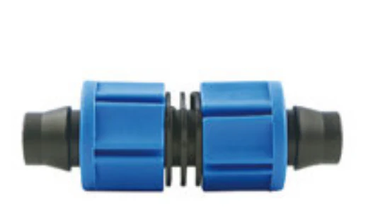
Coupling with catalogue-backed technical fields clearly documented. Compare the exact record, variant and project requirements before a technical enquiry.
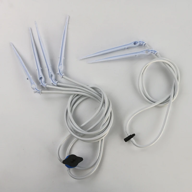
IRRINEX arrow dripper. Working pressure: 0-0.4Mpa; Flow rate: 2 L/H 4L/H 8L/H. An arrow dripper places a drip outlet at a planting point. Select the branch and tubing arrangement from the configuration actually documented for this listing.

IRRINEX impact sprinkler. Size: 1" Male Thread; Working Pressure: 2.0-5.0bar; Spraying Radius: 20-25m. An impact sprinkler distributes water from a selected sprinkler position. Choose the exact connection and nozzle configuration using the recorded pressure and discharge information.
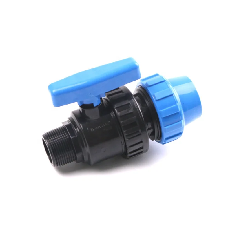
IRRINEX irrigation connection fitting. Diameter: 20 x 1/2"M. A connection fitting joins or terminates selected irrigation components. Choose the named fitting form and match both sides of the connection.