Technical2026-10-11
A clamp-on ultrasonic water flow meter needs a verified pipe description, including the material, outside dimensions, wall thickness and any liner. The transducers sit outside the pipe, but the measurement depends on an acoustic path through the pipe assembly and water. A nominal pipe label and a stable display do not establish that the configured path represents the installation.
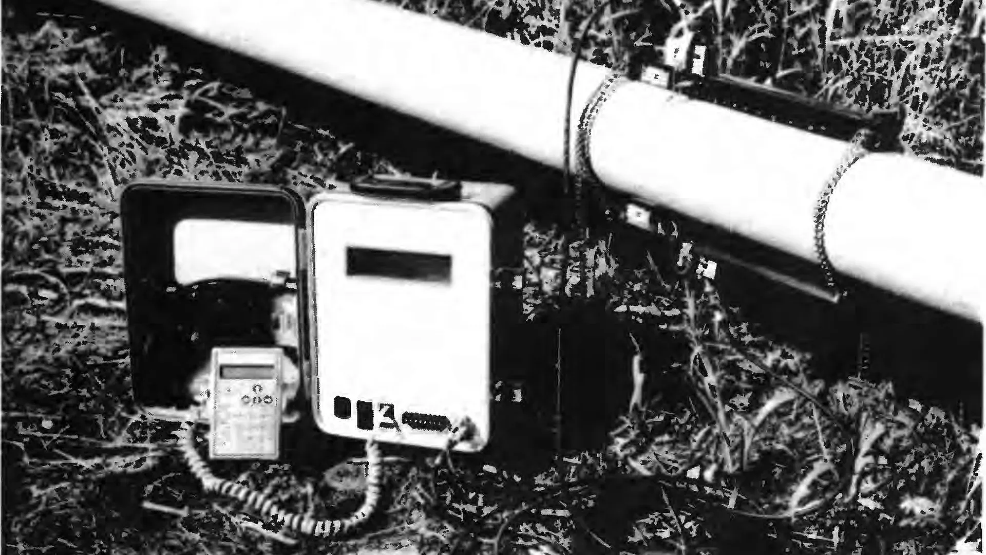
A portable clamp-on ultrasonic flowmeter and its transducers mounted on a six-inch steel irrigation pipe during a USGS field study. This crop comes from figure 1 of USGS Water-Resources Investigations Report 91-4110, published in 1992. The historical photograph shows the measurement setup; it does not substantiate the performance of current instruments. Photo: U.S. Geological Survey.
This guide provides a pipe survey, an original liner-and-diameter calculation and a decision record for agricultural irrigation pipelines. Use it before accepting a proposed clamp-on location. The examples are hypothetical geometry and survey exercises, not an IrriNex meter specification or a field calibration result.
Give the proposed measuring section its own identifier and photograph it from identifiable reference points. A mainline may contain original pipe, replacement spools, repair sleeves and different wall classes. A material description from the IrriNex deep well submersible pump outlet does not necessarily describe the section beside the field manifold.
Record visible markings, installation drawings, procurement records and previous repairs. Label each item by its evidence source. A drawing is useful evidence of the intended construction; a field observation documents what is visible now. If they disagree, keep both records and resolve the discrepancy before treating either as the final configuration input.
| Survey item | Evidence to record | Question to resolve |
|---|---|---|
| Section identity | Field, line, marked position, photographs and nearby permanent references | Can another operator identify the same measuring surface? |
| Pipe construction | Material, grade or construction where known, markings and repair history | Does the evidence describe this spool rather than an adjacent section? |
| Outside dimensions | Measured diameter or circumference, method, units and measurement positions | Does the measurement include a coating, sleeve or insulation? |
| Wall and internal liner | Thickness evidence, liner material, condition and unresolved variations | Are the dimensions and acoustic layers represented separately? |
| Mounting surface and access | Surface condition, available contact area, restraint and service access | Can the specified mounting arrangement be installed and retained? |
The irrigation pipe sizing guide explains the distinction between nominal size, outside diameter and pressure class. A size label is not a measurement of the remaining wall or the clear bore of an old lined pipe. Do not fill unknown fields with the nearest familiar catalogue entry.
For a round, accessible pipe, outside circumference divided by π gives outside diameter. Record where the tape sat and whether the surface was representative. A tape wrapped around insulation or a repair collar measures that outer assembly. It does not reveal the pipe diameter beneath it.
Wall thickness needs an appropriate measurement method and an explicit material basis. When an ultrasonic thickness gauge is used, have a qualified operator confirm the applicable sound-velocity setting, calibration and treatment of coatings or multiple layers. A repeatable displayed thickness can still be based on the wrong material or echo interpretation.
In its 1992 investigation of portable noninvasive pipe flowmeters, the USGS recorded outside circumference and measured wall thickness during site visits; it also collected information on liners and system arrangements. That historical study supports retaining actual pipe evidence. Its equipment-specific performance results and mounting dimensions are not specifications for a current meter.
Agree on measurement positions that represent the proposed transducer contact regions and relevant pipe variation. Keep individual observations as well as any selected value. Do not average evidence of local wall loss into a supposedly uniform wall without review. The survey establishes measurement inputs; it is not a structural fitness assessment or permission to weaken a pressurized pipe.
For the simplified case of a circular pipe with uniform concentric layers, define outside pipe diameter Do, pipe-wall thickness tw and internal liner thickness tl. If Do excludes external coatings, the clear internal diameter is Di = Do − 2tw − 2tl. The factor of two accounts for material on both sides of the cross-section.
Assume a fictional pipe has Do = 200.0 mm, tw = 6.0 mm and a uniform internal liner tl = 3.0 mm. These inputs are stipulated for the calculation; they are not a standard pipe size, measured thickness or approved liner specification.
| Quantity | Liner included | Liner incorrectly omitted |
|---|---|---|
| Outside pipe diameter | 200.0 mm | 200.0 mm |
| Pipe-wall deduction across both sides | 2 × 6.0 = 12.0 mm | 2 × 6.0 = 12.0 mm |
| Liner deduction across both sides | 2 × 3.0 = 6.0 mm | 0.0 mm |
| Calculated clear diameter | 200.0 − 12.0 − 6.0 = 182.0 mm | 200.0 − 12.0 = 188.0 mm |
| Cross-sectional area, πDi²/4 | Approximately 26015.5 mm² | Approximately 27759.1 mm² |
The area ratio is 188² ÷ 182², approximately 1.0670. Omitting this hypothetical liner therefore overstates the geometric area by approximately 6.7%. The diameter difference is 6.0 mm; the area change is not simply that difference expressed as a percentage of diameter.
This is an area calculation, not a prediction that an installed ultrasonic meter will overread by exactly 6.7%. Pipe and liner inputs can also affect the modeled acoustic path and velocity calculation. A complete instrument error assessment must account for those effects and the actual flow conditions.
Keep an external coating separate from an internal liner. An outside coating may affect coupling, the acoustic path and the interpretation of an outside measurement; it does not reduce the internal bore in the same way as the liner in this example. Likewise, irregular deposits and an oval pipe are not automatically represented by the uniform-layer formula.
A list of layer thicknesses does not prove that sound crosses those layers reliably. U.S. Bureau of Reclamation guidance on acoustic-flowmeter selection identifies changing wall or liner thickness as a possible source of significant measurement error. It also explains that external mounts change acoustic transit times and path angles, which the instrument must account for.
Ask the supplier whether the exact transducer and processing arrangement support the documented pipe construction. Include any liner, composite wall, coating, repair sleeve or uncertain interface. A menu containing the general material name is not an approval for every construction sold under that name.
The USGS study also describes air gaps at blistered paint or sleeves as obstacles to signal transfer and notes difficulties associated with internal scale. Treat visible damage and unknown liner bonding as reasons for a more detailed compatibility review. Do not classify an unexplained signal problem as low water flow solely because the meter still displays a number.
Retain the evidence behind a material substitution. If the closest selectable material is proposed because the exact one is absent, request the supplier's documented basis and any required verification. Changing sound-velocity or wall settings until the result matches an expected pump flow destroys the independence of the check.
Use the coupling arrangement specified for the selected instrument and application. Record the couplant or pad, surface preparation, mounting hardware and environmental conditions. Compatibility includes the pipe coating, transducer face, temperature and expected duration of service. A successful short portable test does not establish that the same contact will remain suitable through a season outdoors.
Surface preparation must preserve the pipe's integrity and follow the approved procedure. Do not turn a generic instruction to improve contact into unrestricted scraping, grinding or removal of an unknown protective layer. Record any preparation performed so a later operator understands what changed at the measuring surface.
Follow the selected instrument's mounting mode and spacing calculation using the verified pipe inputs. Preserve both the entered data and the resulting placement instructions. Mark reference points and retain a photograph with a scale where practical. Distinguish the spacing defined by the instrument from an approximate distance between visible housings.
Plan cable routing and restraint so normal field work does not pull a transducer away from its contact surface. Record access for inspection and recoupling if required. If a mounting arrangement must change after the survey, review the affected configuration and verification instead of treating the new position as equivalent.
Confirm the measuring section's hydraulic suitability for the exact meter, including the required filling condition, water characteristics and flow range. Nearby pumps, IrriNex IRX-OOCV hydraulic control valve, reducers and branches belong on the sketch. Their effect is a separate question from pipe material compatibility; good coupling cannot correct an unsuitable velocity profile.
The ultrasonic irrigation meter installation guide covers the wider location and commissioning record. Use the applicable model's requirements for distances and orientation. This pipe survey does not create a universal straight-run requirement for all clamp-on instruments.
Describe ordinary irrigation water and relevant changes, including source blends, entrained air, suspended material or fertilizer injection near the proposed section. The water-testing and filtration brief helps preserve the measurement basis of source information. A general description such as clean water is insufficient if the actual condition changes during operation.
Record the water temperature or other fluid information required by the instrument configuration. Keep these inputs separate from the pipe-material settings. An accepted material setting cannot compensate for an unreviewed change in the measured fluid or a section that becomes partially filled during the intended observation.
The survey should end with a decision and the evidence still needed. A candidate location may be ready for a defined commissioning trial, require further dimensional or material investigation, or be unsuitable for the selected arrangement. Finding a plausible flow number is not enough to close a missing-liner question.
| Survey finding | Next action | Evidence needed to close the item |
|---|---|---|
| Pipe and liner documented; configuration supported | Proceed to the agreed installation and verification trial | Saved inputs, mounting record, operating conditions and acceptance results |
| Wall readings vary or conflict with the drawing | Review the measurements and local pipe condition | Resolved dimension basis or a different measuring section |
| Liner construction or bonding is unknown | Request additional records, investigation or supplier review | Documented compatibility evidence; uncertainty remains open until resolved |
| Diagnostic requirements fail despite approved setup | Investigate the path and operating condition before using the value | Explained cause and repeat verification, or rejection of the location |
During the trial, retain the diagnostic quantities actually supplied by the meter and their documented acceptance criteria. A strong signal is useful evidence about reception; it does not independently certify pipe dimensions, flow profile or volumetric accuracy. Preserve failed attempts alongside successful ones when they reveal a condition that can recur.
Link the accepted measuring section to the irrigation pipeline hydraulic record where appropriate, while keeping meter settings distinct from design assumptions. Revisit the survey after a spool replacement, relining, repair or mounting relocation that changes the documented measurement path.
Only if the selected input explicitly expects that nominal designation and resolves it using the correct documented construction. Otherwise supply the verified dimension the instrument requests. Nominal size and actual outside diameter are not interchangeable labels.
No universal compatibility follows from the mounting method. Check liner material, thickness, condition and interfaces against the exact transducer arrangement. Unknown bonding or irregular deposits may require investigation or another location.
No. The display can be repeatable while depending on an incorrect dimension or material setting. Verify the inputs, mounting, diagnostics and operating conditions, then apply the agreed independent performance check for the intended use.
The meter calculates inside diameter ($ID = OD - 2 \times \text{Wall}$) to determine flow area ($A = \pi ID^2 / 4$). Flow area is a squared term; an error of just 1.0mm on pipe wall thickness produces a 6% to 12% error in calculated flow rate ($m^3/h$).
PVC: $2,380\text{ m/s}$; HDPE (Polyethylene): $1,900 - 2,050\text{ m/s}$; Carbon Steel: $3,230\text{ m/s}$; Ductile Iron: $3,000\text{ m/s}$; Water at 20°C: $1,482\text{ m/s}$. The meter uses these values to calculate sonic refraction angles.
Internal rust nodules, pits, and scale scatter the high-frequency acoustic beam, while microscopic air voids between the pipe metal and cement mortar lining reflect the sonic pulse entirely, preventing sound from entering the water column.
Check the meter's diagnostic menu for 'Signal Strength' (typically $> 60\text{ dB}$) and 'Transit Time Ratio' ($t_1 / t_2$ should read between $97\%$ and $103\%$). Ratios outside this range indicate acoustic distortion or wrong wall thickness entry.
Products relevant to this irrigation guide.
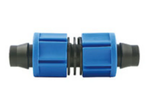
Coupling with catalogue-backed technical fields clearly documented. Compare the exact record, variant and project requirements before a technical enquiry.
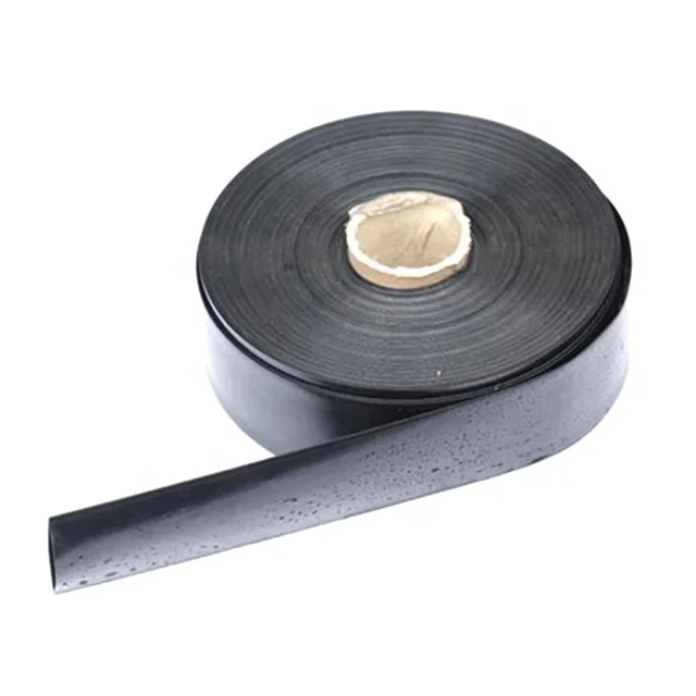
IRRINEX irrigation pipe or hose. Size: 20-75mm; Wall thickness: 0.15 - 0.5mm; Fold diameter: N32 - N120; Hole spacing: 300mm 500mm. Pipe or hose conveys water between irrigation components. Confirm the actual line type and dimensions before selecting connections or planning an installation.
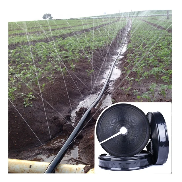
IRRINEX irrigation spray hose or tape. Size: Outside Diameter 25mm; Flow rate: 0.5 m3/h/10m; Spray Diameter: 1.5-2.0m; Spray Length: 40m. Spray hose or tape is a distributed watering component for a selected planting layout. Use the stated dimensions and operating information for the exact configuration.
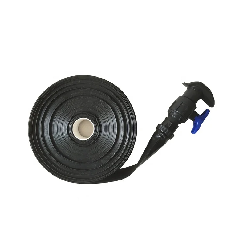
IRRINEX irrigation spray hose or tape. diameter: 20-75mm; Size: 1/2"- 2 1/2"; Thickness: 0.15mm-0.5mm; Fold diameter: N32mm-N120mm. Spray hose or tape is a distributed watering component for a selected planting layout. Use the stated dimensions and operating information for the exact configuration.