Technical2026-10-21
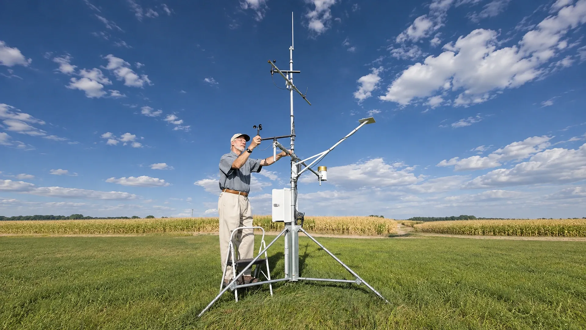
A radio survey for wireless irrigation sensors must prove that every planned node can deliver usable packets through the farm’s real canopy, terrain and operating conditions. Do not accept a catalogue range as field coverage. Map each soil-moisture, flow, pressure and weather node; test it at its proposed height and antenna orientation; record signal quality and packet delivery; and keep enough margin for full foliage, wet leaves, moving machinery and seasonal change. A passing survey ends with an approved gateway, repeater and fallback plan, not merely a phone screenshot showing “connected.”
A technician services a real agricultural telemetry and weather station in a crop field. The equipment illustrates the antennas, mast, enclosure and field obstructions that a radio survey must document; it does not represent the hypothetical readings in this guide. Photo: USDA Agricultural Research Service, public domain. The portrait source was extended horizontally with a limited AI edit; the original equipment and technician remain the factual photographic base.
This guide is for farms planning wireless irrigation sensors or remote moisture monitoring across orchards, vineyards, row crops and uneven ground. It explains a repeatable acceptance method rather than promising a universal distance. Radio performance depends on frequency, permitted transmit power, receiver sensitivity, antenna system, installation height, obstructions, interference and the reliability target chosen for the irrigation decision.
Begin with the decision that depends on each link. A soil-moisture point used for weekly review can tolerate a different delay from a pressure alarm intended to warn an operator during a short irrigation set. Write the maximum acceptable data age, reporting interval and missing-packet window for every measurement. If a node can store readings and forward them later, distinguish data completeness from real-time alarm availability.
Specify an acceptance metric before walking the field. Packet delivery ratio is usually more useful than one instantaneous signal-strength value: received packets divided by expected packets during a defined test. Also record the radio’s signal indicator, noise or signal-to-noise value, retry count, latency and battery voltage when available. Keep raw observations because a vendor dashboard may simplify them into colored bars that cannot be compared after firmware or gateway changes.
Give every proposed device a stable field identifier. Record sensor type, irrigation zone, coordinates, ground elevation, mounting height, antenna model, cable length, orientation, power source, reporting interval and the decision it supports. Keep the physical sensor identity separate from the measurement location so that a replacement does not erase location history. The same discipline used in a controller wiring and station map prevents a radio fault from being confused with a mislabeled IrriNex IRX-OOCV hydraulic control valve or sensor.
The survey register should also list gateway candidates, available backhaul, safe mounting structures, service access, lightning and grounding review, and whether the antenna can remain above future crop growth. Photograph each proposed position in the four cardinal directions. Mark structures that may change, such as stacked bins, parked machinery, temporary tunnels or seasonal shade cloth.
| Field | Why it matters | Record at each test |
|---|---|---|
| Node and irrigation zone | Links radio evidence to an operating decision | Stable ID, sensor type and valve or block |
| Position and height | Small moves can change line of sight and Fresnel clearance | Coordinates, elevation, sensor and antenna height |
| Radio setup | Results are valid only for the tested configuration | Channel, data rate, power, antenna, cable and firmware |
| Traffic test | A brief connection can hide losses | Expected, received, retries, latency and test duration |
| Environment | Canopy and equipment change attenuation | Leaf stage, wet or dry foliage, machinery and weather |
| Decision | Turns measurements into an installable design | Pass, relocate, elevate, repeat, or gateway/repeater required |
Draw a simple terrain profile between each node and gateway candidate. Note ridges, depressions, cut banks, buildings, tanks, metal screens and dense tree rows. A direct visual line is useful, but radio energy also occupies a volume around that line. A path that just skims a ridge or canopy can therefore be fragile even when the two antennas appear visible. Record the obstruction rather than claiming a precise clearance unless a qualified radio design tool and verified inputs are being used.
Orchard and vineyard rows form directional corridors. Test a node along the row, across multiple rows and diagonally toward the gateway. Trunks, trellis wire, wet foliage and fruit load do not create the same path in every direction. In rolling fields, test both the near face and the reverse slope. A gateway that performs well on the headland may still miss a sensor only a short map distance away below a terrace.
Mark expected full canopy height and width, cover-crop growth, tunnel film, movable irrigation equipment and harvest traffic. A leaf-off orchard survey needs a seasonal margin or a second survey at full canopy. If the installation will remain for years, include expected tree growth and planned structures. Treat a new shed, solar array or water tank as a trigger for re-survey.
Gateway elevation often improves paths because it clears low obstacles, but height alone is not a design. Confirm that the structure is permitted, stable and safely accessible, that the antenna cable run is suitable, and that power and backhaul remain reliable. A higher antenna connected through excessive or unsuitable cable can lose part of the expected benefit. Document grounding and surge protection with the responsible electrical or radio professional.
Washington State University describes private orchard sensing networks in which field nodes report through a gateway and recommends elevated gateway antennas to reduce obstructions. Its orchard sensing-network overview supports the obstruction and elevation principles used here. It does not establish a guaranteed range for another farm, radio or antenna.
Test at least two gateway candidates when practical. One central high point may reduce radio distance, while a service building may offer better power, internet access and maintenance. Score coverage, backhaul, electrical reliability, safe access and future obstruction separately. Avoid hiding a poor field link behind a gateway site selected only for convenience.
Use the intended production hardware and settings. Fix the node at the planned mounting height, use the specified antenna and cable, set the actual channel or data rate, and transmit the normal message size and interval. A survey performed with a handheld radio, a temporary high mast or an engineering mode at a different power does not verify the final installation. Record firmware and configuration exports so the test can be reproduced.
Synchronize clocks before the trial. The gateway log, node sequence counter and survey notes must refer to the same interval. If you already reconcile pulse or interval records using the flow-meter pulse workflow, apply the same rule here: retain counts and timestamps before a dashboard aggregates them.
Where the equipment permits it, record channel noise or spectrum occupancy with the test node silent. Repeat during irrigation, IrriNex deep well submersible pump starts, harvest operations and normal facility activity. Interference can be intermittent, so a clear five-minute window is not proof of a quiet channel. Follow applicable radio rules and the equipment instructions; this guide does not authorize channel, power or antenna changes.
At every planned node position, send a defined series rather than one message. A useful survey sheet states the count, interval and duration before testing. For example, 120 expected messages at 30-second intervals is a one-hour test. If 115 arrive, the observed delivery ratio is 115 ÷ 120 = 95.8%. This is a teaching calculation, not a universal acceptance threshold. The project must set a target that matches its alarm and control consequences.
Repeat the series with normal obstructions present. Close the intended enclosure, place the antenna beside the actual pole or tree, and park equipment where it normally operates. Do not hold the node above your head. Walk away after verifying the sequence start so a person standing beside the antenna does not become part of the test configuration.
| Location | Expected / received | Delivery | Observed condition | Decision |
|---|---|---|---|---|
| S-01 upper block | 120 / 120 | 100.0% | Dry, leaf-on, gateway A | Retest wet canopy; provisional pass |
| S-02 hollow | 120 / 109 | 90.8% | Reverse slope; retries clustered | Test higher mount and gateway B |
| P-03 pump outlet | 120 / 117 | 97.5% | Losses during motor starts | Investigate interference and power |
| F-04 far headland | 120 / 88 | 73.3% | Machinery crossed path | Do not accept; reroute or add coverage |
| R-05 repeater trial | 120 / 119 | 99.2% | Same node via surveyed relay | Verify power, margin and failure alarm |
A connected packet only proves that one transmission worked. Review the distribution of signal and noise readings over the complete run, not the best value. If readings sit near the radio’s documented limit, a small seasonal change can remove the link. Use the device documentation to interpret its metrics because scales are not interchangeable between radios. Do not invent a generic “good dBm” rule.
Look for bursts of missing sequence numbers. Even a high overall delivery ratio can be unsuitable for a short alarm window if ten consecutive messages vanish. Record the longest loss burst, recovery time and whether stored data later arrived. Design alert behavior with the remote irrigation alarm guide so a silent sensor, stale reading and confirmed hydraulic problem produce distinct operator actions.
When a link fails, change one variable at a time. First repeat the baseline. Then test a modest approved antenna-height change, an alternative gateway, or a surveyed relay position. Record every configuration as a new row. Moving the node, changing the data rate and adding a repeater simultaneously may produce a connection, but it destroys the evidence needed to know what solved the problem.
| Option | Use when | Verify before acceptance | Operational cost |
|---|---|---|---|
| Relocate node slightly | A local trunk, bank or metal object blocks the path | Sensor still represents the intended hydraulic or soil zone | New coordinates and installation protection |
| Raise approved antenna | Low obstacles dominate and structure allows safe mounting | Cable loss, stability, lightning and service access | Mast inspection and safe work method |
| Choose alternate gateway | Terrain creates shadow behind a ridge or orchard block | Backhaul, power, total-node load and all other links | Second site maintenance |
| Add surveyed relay | No single gateway path meets the target | Relay power, both radio legs, failure alarm and stored data | Another critical field asset |
| Wired segment | Critical short path remains unreliable or radio is unsuitable | Cable route, surge, isolation and interface compatibility | Trenching and cable maintenance |
Radio convenience must not pull a soil probe away from the soil, IrriNex EMT-PC dripper and management zone it is meant to represent. Use the remote moisture sensor placement guide to preserve agronomic meaning. It may be better to move an external antenna or add a relay than to move the measurement point into an unrepresentative wet spot.
Foliage contains water and changes with the season. A robust plan either surveys the worst expected canopy or reserves a documented margin and schedules a full-canopy verification. Wet leaves can differ from dry leaves, and wind can move branches into and out of the path. Record leaf stage, recent rain or irrigation, wind and crop height in every test row.
If the first survey occurs before planting or during dormancy, mark the result “design survey,” not final acceptance. Install temporary reference nodes or return when the actual canopy exists. Where over-tree sprinklers or cooling systems wet the radio path, test during their operation if safe and permitted. Keep the hydraulic schedule separate from radio testing by following the irrigation controller selection guide for control architecture decisions.
After permanent mounting, repeat the accepted test at every node. Compare coordinates, height, antenna direction, cable and firmware with the survey register. Confirm that the correct measurement appears under the correct field and unit, that timestamps are current, and that a disconnected node produces the intended stale-data alarm. A radio link cannot prove that the pressure transducer, flow meter or soil probe is installed correctly.
Run one controlled irrigation event and compare node data with independent field evidence. Confirm valve, flow and pressure separately; do not issue a control command merely to test coverage unless the operating team has approved the hydraulic action. Record installation photographs, log exports, exceptions, retests and the person accepting each link.
State what the controller or operator does when data is missing, late or implausible. Depending on the process, the safe response may be a time-limited schedule, manual inspection, inhibited automation or a conservative operating state. The correct choice belongs in the farm’s control and agronomy plan. A last-known sensor value must not silently remain “current.”
Use an evidence ladder when data disappears. Check node power and local logging, then the field radio leg, gateway service, backhaul and cloud ingestion. A healthy signal indicator cannot rule out a dead sensor, and a visible dashboard gap cannot prove poor radio coverage. Compare sequence counters, gateway receive logs and stored node records before replacing hardware.
Clustered losses during pump starts may indicate interference, voltage drop or grounding problems; they do not identify the cause by themselves. A seasonal decline isolated to cross-row orchard nodes points toward canopy or path change, but still needs a repeat test. Keep troubleshooting observations beside the original acceptance record so each hypothesis can be tested instead of becoming folklore.
Set re-survey triggers: canopy growth, new buildings, relocated gateways, changed antennas, radio or firmware configuration, new machinery routes, repeated loss bursts, battery-system changes and unexplained stale-data alarms. Review critical links before the high-demand irrigation season. Test a sample of lower-consequence nodes and all nodes that have crossed the project’s warning limit.
A complete handover includes the map, node and gateway register, production configuration, raw test logs, calculations, photographs, exceptions, repair history, fallback rules and next review date. It gives the next technician enough evidence to repeat the survey without guessing. That record is the practical difference between wireless irrigation sensors that merely connect on installation day and a remote monitoring network operators can trust throughout the season.
No single distance is defensible without the specific radio, antenna, rules and field path. Treat advertised line-of-sight distance as a test condition, then verify the proposed locations with production hardware and a stated packet-delivery requirement.
No. Signal and noise readings help explain margin, while a counted packet series shows delivery, bursts and recovery over time. Use both and preserve the raw log.
Survey near the worst expected canopy when possible. If design work happens at leaf-off, document the limitation, keep margin and schedule a full-canopy or wet-canopy verification before relying on the link for critical alarms.
Foliage absorption and scattering: high moisture content inside leaves and dense branch wood absorbs radio wave energy (especially at 2.4 GHz, which suffers 15 to 30 dB of attenuation per 100 meters). Sub-GHz (868/915 MHz) frequencies penetrate foliage with much lower path loss.
The Fresnel zone is the elliptical volume of space between transmitter and receiver antennas through which radio waves propagate. At least 60% of this radius must be completely clear of tree canopies, hills, and metal buildings to prevent phase cancellation.
RSSI: Excellent: $>-85\text{ dBm}$; Acceptable: $-85\text{ to } -110\text{ dBm}$; Unreliable: $<-115\text{ dBm}$. SNR: Positive ($>+5\text{ dB}$) is ideal; for LoRa modulation, signals remain receivable down to $-10\text{ dB}$ to $-15\text{ dB}$.
Deploy a directional Yagi antenna on distant or shadowed sensor nodes transmitting to a fixed central gateway tower. The focused beam adds 9 to 14 dBi of passive gain, doubling transmission distance through valleys without increasing battery power.
Products relevant to this irrigation guide.
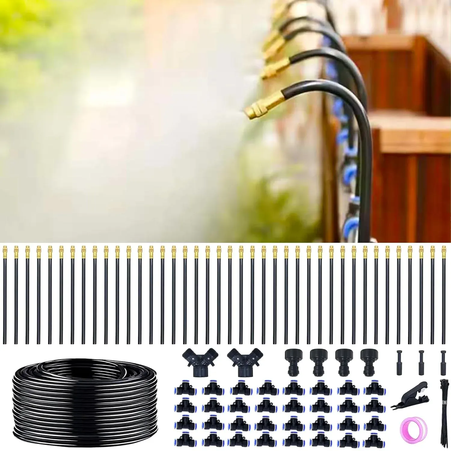
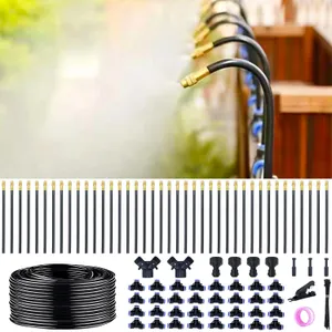
The IrriNex drip irrigation system kit combines 200 ft and 5/16-inch for raised beds. Review listed components and connection details before ordering.
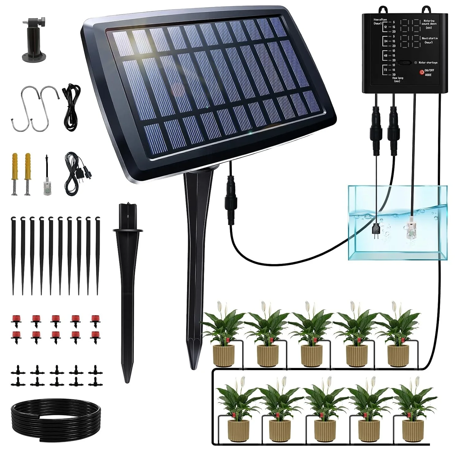
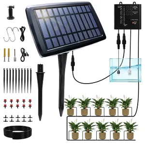
The IrriNex drip irrigation system kit combines 49 ft and 15 pots for raised beds. Review listed components and connection details before ordering.
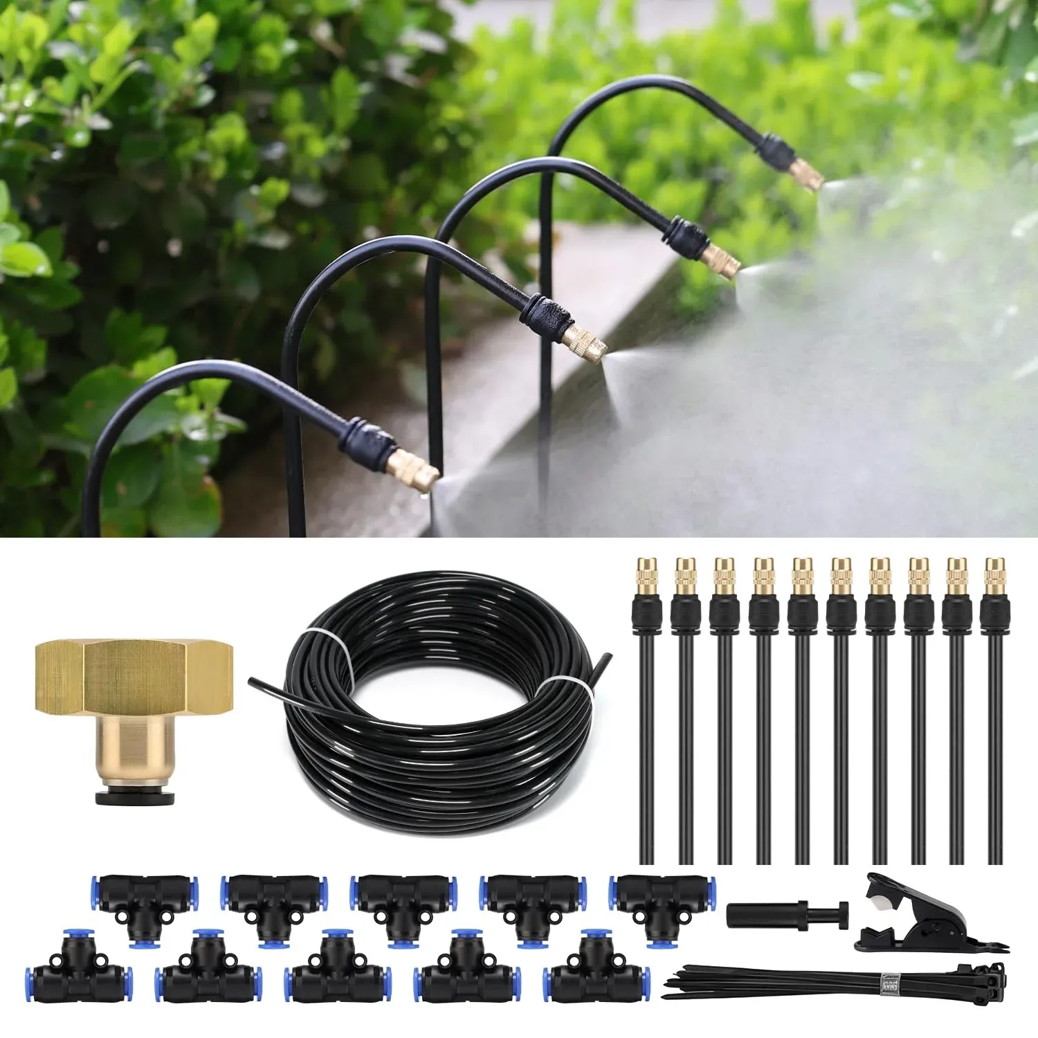
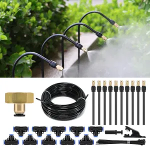
The IrriNex drip irrigation system kit combines 30 ft and 50 ft for vegetable gardens. Review listed components and connection details before ordering.
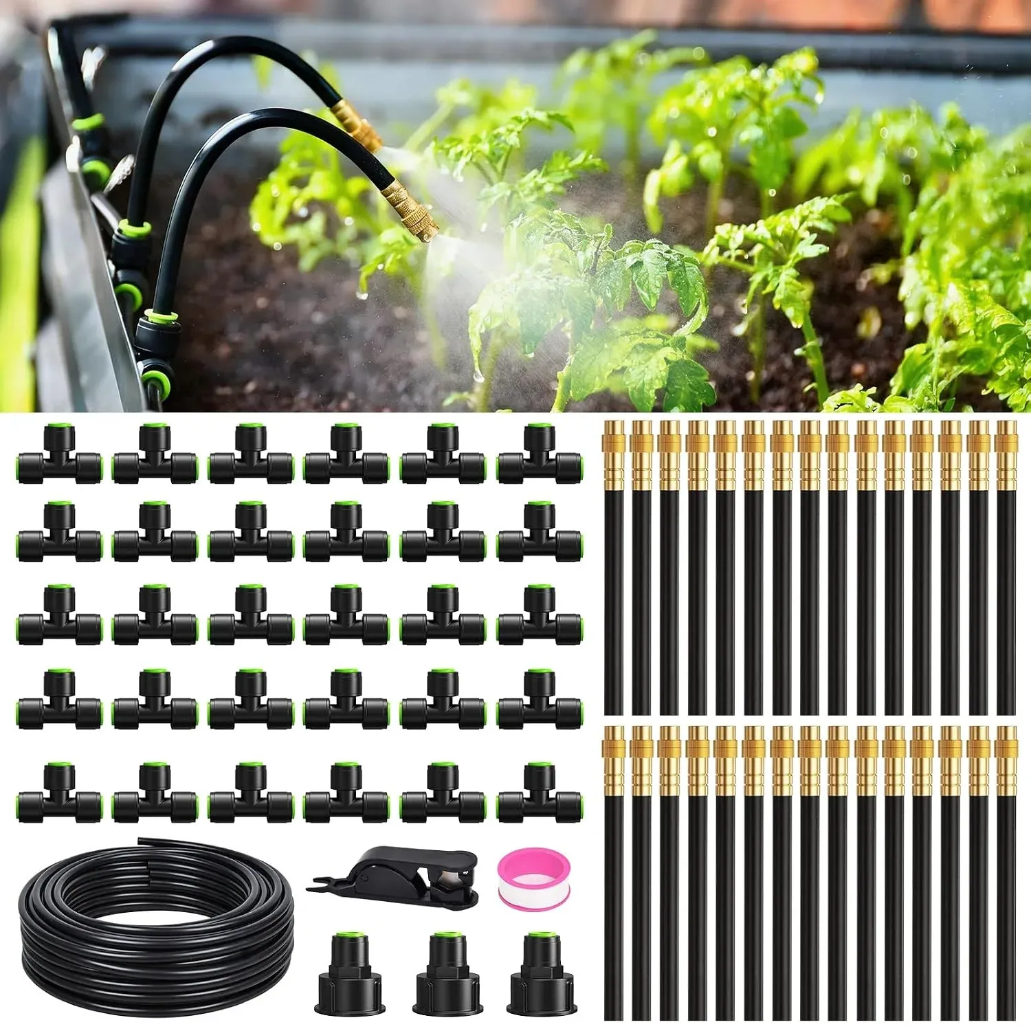
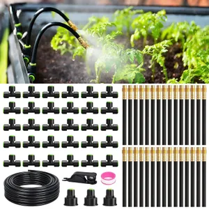
The IrriNex drip irrigation system kit combines 100 ft and 8 ft for raised beds. Review listed components and connection details before ordering.