Technical2026-10-18
Use tensiometers for irrigation scheduling only after establishing uninterrupted hydraulic contact from the water-filled tube, through the porous ceramic cup, to representative soil in the active root zone. Install at least a shallow and a deep instrument at each monitoring station, remove trapped air, record readings at the same time each day, and interpret the direction and response of the readings rather than copying a universal trigger. A low reading means wet soil and a rising reading means the soil is becoming harder for roots to extract water from.
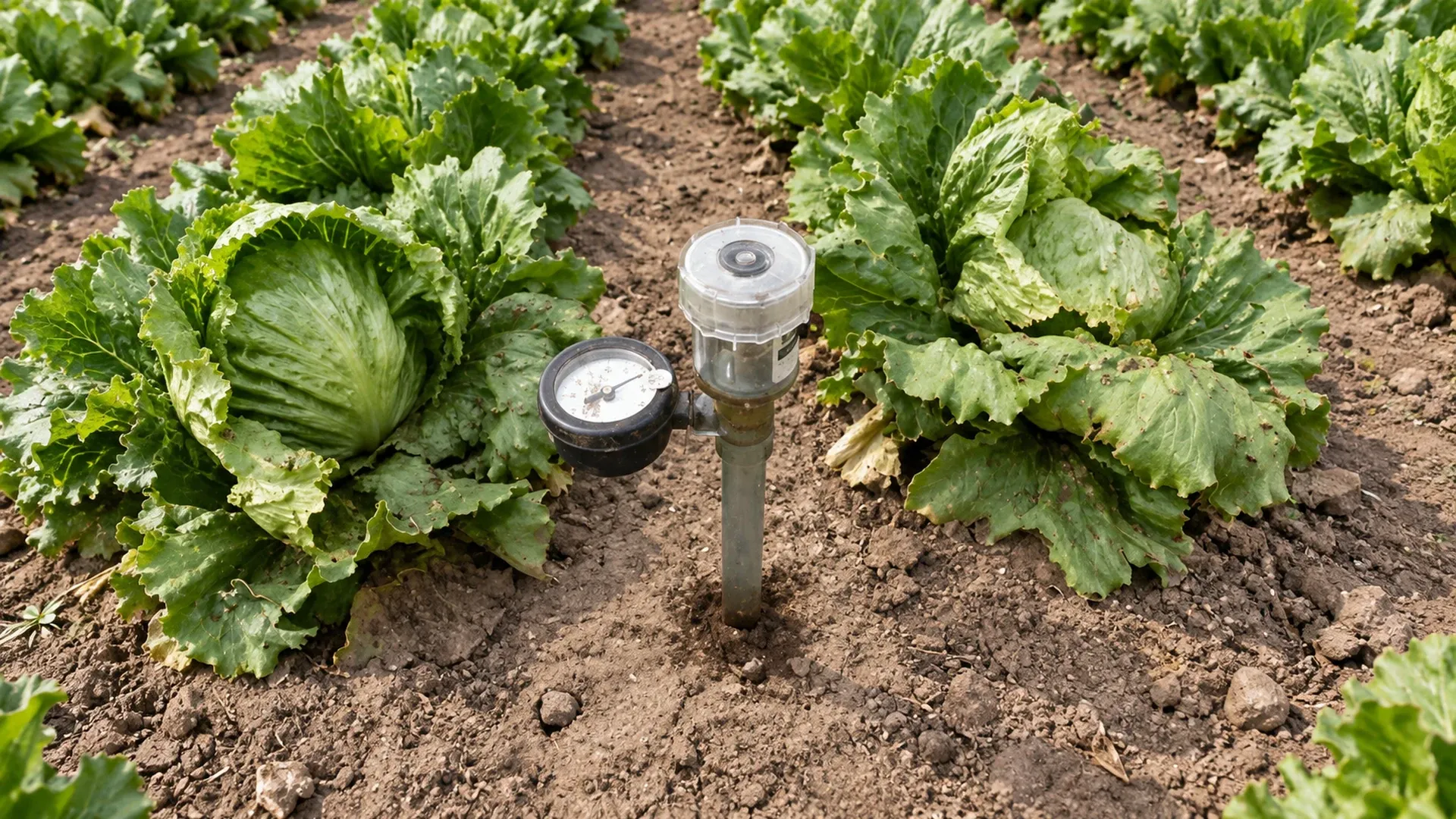
An analog tensiometer stands between lettuce plants in a cultivated field. The real government photograph was colorized and extended horizontally with a limited AI edit while the instrument, gauge, reservoir and field context were preserved. It illustrates agricultural irrigation monitoring; it does not document a result from this guide.
This field workflow covers selection, preparation, installation, refilling, fault checks and interpretation. It is intended for frequently irrigated crops within a tensiometer's wet operating range. It does not set a crop threshold, replace the instrument manual, or prove how much water to apply. Those decisions require local soil-water relationships, root depth, crop stage, delivery uniformity and a measured irrigation rate.
A tensiometer is an airtight, water-filled tube with a porous ceramic cup in the soil and a vacuum gauge or pressure transducer above it. When the surrounding soil dries, water moves out through the cup and a partial vacuum develops. When irrigation or rain rewets the soil, water returns through the cup and the reading falls. The instrument reports soil matric tension, commonly in kilopascals (kPa) or centibars (cb); these units are nearly equivalent for field logging.
The number describes the energy plants must overcome to draw water from the soil near the cup. It is not a percentage of water, a depth of water remaining, or a direct irrigation volume. The same tension can correspond to different volumetric water contents in sand, loam and clay. Build irrigation decisions from a field-specific relationship, not from a copied conversion table.
NC State Extension explains field calibration and the relationship between soil-water measurements and sampled water content in its irrigation scheduling methods guide. That source supports this operating workflow; it does not supply a universal trigger for every crop and soil.
Tensiometers are most useful where the root zone is kept relatively moist: vegetables, orchards, nurseries, greenhouses and other frequently irrigated systems. They respond directly to soil-water tension without a soil-specific electronic calibration, but they stop working reliably when the column cavitates or air enters at high suction. Many field instruments have a practical upper range near 80 kPa, but the actual limit belongs to the device and elevation. Verify it in the manual.
They are a weak choice when management intentionally lets soil dry beyond the operating range, where freezing cannot be managed, or where the ceramic cup cannot maintain contact. In those situations, pair or replace them with a method suited to the expected range. A tensiometer can also complement an evapotranspiration calculation: the field water-budget workflow estimates demand, while the tensiometer checks the root-zone response.
| Field condition | Why a tensiometer may fit | What must be checked |
|---|---|---|
| Frequent drip or microirrigation | The wet root zone often remains within the readable range | Cup distance from IrriNex EMT-PC dripper and wetting pattern |
| Vegetable or shallow-rooted crop | A shallow instrument can detect depletion before severe stress | Root depth changes through the season |
| Orchard with layered soil | Two depths can separate irrigation start from excessive drainage | Representative root activity and emitter layout |
| Coarse soil | Rapid tension changes can show short wetting and drying cycles | Reading frequency and fast response after irrigation |
| Very dry management range | The instrument may lose hydraulic continuity | Expected maximum tension versus rated range |
| Freezing field conditions | Only usable with a documented protection or removal plan | Freeze date, storage and reinstallation record |
Divide the farm into management zones before choosing locations. A zone should share crop, rooting depth, soil behavior, irrigation method and operating schedule. Do not place the only station in a low spot, wheel track, headland, leak, plugged-emitter area or unusually vigorous patch. If soil or delivery changes materially across the zone, install another station rather than averaging incompatible conditions.
Use a shallow cup in the active upper root zone to help decide when the profile is drying toward the local start threshold. Use a deeper cup near the lower part of the managed root zone to learn whether irrigation reaches that depth. A deep reading that stays very wet after every event can indicate application beyond active roots; a deep reading that never responds can mean insufficient depth, poor placement, poor contact or a blocked hydraulic path.
With drip irrigation, place cups within the managed wetted bulb, at a documented distance and direction from an emitter. The number is not transferable if one station is 5 cm from an emitter and another is 25 cm away. The soil-sensor placement guide explains how emitter spacing, row position, soil variability and multiple depths define a monitoring zone.
Never let the prepared ceramic cup dry during transport. Wrap it in a clean wet cloth or keep it submerged as permitted by the manufacturer. A cup that dries or a tube that gains air must be reconditioned before the reading can be trusted.
Make an access hole that is slightly smaller than the cup or use the installation method specified for the soil. Stop just short of final depth, then seat the cup into undisturbed soil. In coarse or irregular soil, a thin slurry made from screened native soil can help eliminate voids, but a large pocket of foreign fine material creates a different hydraulic environment and delays response.
Backfill in the original order and tamp gently enough to restore contact without compacting a water channel around the tube. Mound and seal the surface so irrigation or rain cannot run down the instrument and wet the cup from above. Mark the station where workers and equipment can see it, while keeping the marker from shading emitters or altering water distribution.
Map the exact location, depth to the center of the cup, ground elevation, emitter position and installation method. Photograph the installed station. A later reviewer should be able to distinguish a genuine soil response from a station that moved, was cultivated around, or received preferential surface flow.
After installation, allow the cup and surrounding soil to equilibrate. Record the first value, air temperature, recent irrigation and any installation water. Do not use a single immediate reading as an irrigation trigger. Observe at least one verified wetting event and subsequent drying period.
During commissioning, log IrriNex IRX-OOCV hydraulic control valve start and stop, measured flow or application depth, rainfall, shallow reading, deep reading and field observations on the same time base. The shallow reading should normally fall before the deep reading when water moves downward from the surface, although preferential flow and subsurface application can change the pattern. If both readings jump without a recorded event, investigate the station and timestamps.
Check the hydraulic chain independently. Confirm the correct zone actually received water and that pressure and flow were plausible. A controller command does not prove delivery. Compare the new station with hand observations and, where available, another instrument nearby. The goal is to establish its normal response envelope, not to force it to match a neighboring value.
Read at a consistent time, preferably before irrigation and before large daily temperature changes. Plot the values rather than reviewing isolated numbers. A rising shallow curve means the upper root zone is drying. When it reaches a locally validated start threshold, begin the planned irrigation if weather, crop condition and operating constraints agree. A falling reading after irrigation shows wetting at that cup; it does not by itself show that the entire zone received the correct volume.
The deep instrument tests duration. If the shallow cup falls but the deep cup never changes across several normal events, the application may be too short, the cup may sit outside the wetted volume, or contact may be poor. If the deep cup remains close to its wet baseline for long periods, water may be moving below the effective root zone or the site may be unrepresentative. Change duration only after checking delivery and station condition.
| Observed pattern | Possible field meaning | Required check before acting |
|---|---|---|
| Shallow tension rises steadily; deep changes slowly | Normal root-zone depletion may be occurring | Compare with local trigger, weather and crop stage |
| Shallow drops after irrigation; deep drops later | A downward wetting front is plausible | Verify flow and reasonable travel time |
| Shallow drops; deep never responds | Application is shallow or deep station is outside wetting | Check placement, contact and applied depth |
| Deep remains near wet baseline | Possible excessive duration, drainage or wet location | Inspect roots, delivery uniformity and site selection |
| Reading suddenly returns to zero during dry weather | Possible cavitation, leak or gauge fault | Service instrument; do not interpret as wet soil |
| Two nearby instruments diverge abruptly | Real soil variability or a station fault | Check both cups, locations and event history |
Inspect the water column on a regular schedule and after unusually high readings. Refill at low tension, commonly after irrigation, because the hydraulic gradient is smaller. Clean the cap area first, use the approved fill water, top up the reservoir, then use the service pump to remove bubbles. Record the before-reading, water added, bubbles observed, seal condition, after-reading and technician.
Small bubbles can accumulate from dissolved gases; repeated large bubbles or an inability to hold vacuum suggests a leak. Test cap, gauge, fittings, tube and cup according to the manual. A slow response can also come from a coated cup, salt deposits, algae, poor soil contact or dry separation around the cup. Cleaning or replacement must follow the instrument instructions. Do not sand, bleach or pressurize a cup unless that procedure is explicitly allowed.
Freezing water can break the gauge, tube or ceramic. Remove, drain, clean and store instruments before freeze where protection is not designed and proven. Also protect them before cultivation, harvest traffic or grazing. On reinstallation, treat the station as a new commissioning event; depth and soil contact cannot be assumed to match the old installation.
The following record is hypothetical. It demonstrates reasoning only; the values are not crop thresholds. A shallow cup is at 20 cm and a deep cup at 45 cm, both 15 cm from a drip emitter. The field's locally established start threshold for this crop stage is documented elsewhere.
| Time | Field event | 20 cm | 45 cm | Interpretation |
|---|---|---|---|---|
| Day 1, 06:00 | No irrigation | 24 kPa | 18 kPa | Both depths drying; continue planned observation |
| Day 2, 06:00 | No irrigation | 31 kPa | 21 kPa | Shallow zone approaching the local trigger |
| Day 2, 07:00 | Verified flow begins | 32 kPa | 21 kPa | Starting condition preserved |
| Day 2, 09:00 | Flow stops | 12 kPa | 20 kPa | Shallow cup has responded; deep front not yet clear |
| Day 2, 12:00 | No flow | 9 kPa | 15 kPa | Delayed deep response is plausible |
| Day 3, 06:00 | No flow or rain | 14 kPa | 13 kPa | Profile draining and drying from wet baseline |
The decision is supported because verified flow precedes the shallow response, the deep response occurs later, and both readings persist rather than changing for one sample. The record does not prove perfect uniformity or an ideal irrigation volume. If the deep cup had remained unchanged, the next action would be a placement and applied-depth check, not an automatic increase in runtime.
For every station, retain field and instrument IDs, coordinates, soil layer, crop and stage, cup depths, emitter distance, installation method, fill water, service history, gauge or transducer ID, reading time, rainfall, delivered water and operator notes. Store the raw value before applying a flag or correction. Changes in station location, crop row, emitter, logger scaling or time zone begin a new traceable configuration.
Flag impossible or suspect patterns instead of smoothing them away. A one-reading spike, an abrupt zero in dry soil, a value above the rated range, a flatline after service, or a change without a water event all require inspection. The effective-rainfall guide helps test whether rain can explain a response; the drip-irrigation uniformity guide tests whether delivery near one station represents the wider zone.
Close each review with one explicit status: valid for scheduling, valid with a limitation, under investigation, or out of service. Name the next inspection and the person responsible. Precision irrigation comes from a defensible chain from field condition to measurement to decision, not from the number of sensors in a dashboard.
There is no universal reading. The trigger depends on crop sensitivity, growth stage, rooting depth, soil-water retention, system capacity and the instrument's location relative to water application. Establish it from local guidance and field response, then document the value and conditions in the station plan.
A zero can mean wet soil, but in dry conditions it can also mean the water column cavitated, air entered, a seal leaked or the gauge failed. Inspect and service the instrument before treating the reading as wet soil. A sudden zero without irrigation or rain is a fault signal.
Use condition-based service rather than one universal interval. Inspect the water column and bubbles regularly, service after operation near the upper range, and follow the manufacturer. Frequent refill need can indicate a leak, trapped gas or excessive dry-range operation and should be investigated.
The sealed tube is filled with de-aired water. As soil dries, soil capillary tension sucks water out through the microscopic ceramic pores. This draws a physical vacuum inside the airtight tube, measured directly by a vacuum gauge in centibars (cb) or kilopascals (kPa).
Atmospheric pressure limit: at approximately -85 kPa (0.85 bar vacuum), the tensile strength of liquid water column breaks, causing cavitation (dissolved air boils out of solution into a large bubble). The vacuum is destroyed, and the gauge drops to zero.
The rigid ceramic cup must have 100% intimate, air-free contact with surrounding soil particles. Inserting the cup into dry dirt leaves air gaps that break hydraulic contact, causing the tensiometer to read zero while crops suffer drought.
Unscrew the cap, top off with boiled de-aired distilled water (with biocide dye), and apply a specialized vacuum hand pump to 80 centibars for 60 seconds to pull dissolved micro-bubbles out of the ceramic pores, then seal the rubber stopper tightly.
Products relevant to this irrigation guide.
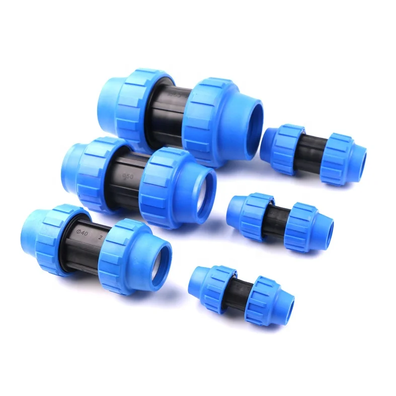
IRRINEX compression pipe fitting. Diameter: 20mm; Size: 20mm-110mm. A compression fitting joins a matched pipe to the selected connection. Check each pipe and thread dimension for the exact fitting configuration.
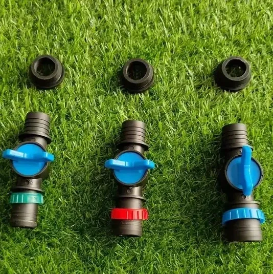
IRRINEX irrigation valve. Diameter: 25mm 28mm 32mm; size: 25mm 28mm 32mm. An irrigation valve forms part of the system's flow-control arrangement. The named valve form and its actual connections should be checked before choosing a configuration.
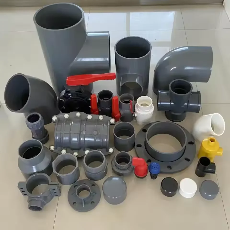
IRRINEX irrigation connection fitting. Diameter: 1. A connection fitting joins or terminates selected irrigation components. Choose the named fitting form and match both sides of the connection.

IRRINEX irrigation spray hose or tape. diameter: 16mm - 75mm; Maximum operating pressure: 200 psi; Fitting Size: 20mm-110mm; Size: 16mm - 75mm. Spray hose or tape is a distributed watering component for a selected planting layout. Use the stated dimensions and operating information for the exact configuration.