Manual vs Motorized Irrigation Valves: Choose Actuation for Remote Locations
Choose manual or motorized irrigation valves by checking the required operating response, the valve's mechanical load, available power and the evidence of actual valve position. A remote location increases the importance of service access and recovery after a fault. It does not automatically make an electric actuator the best choice, nor does a motorized label establish remote communication or automatic closure during a power failure.
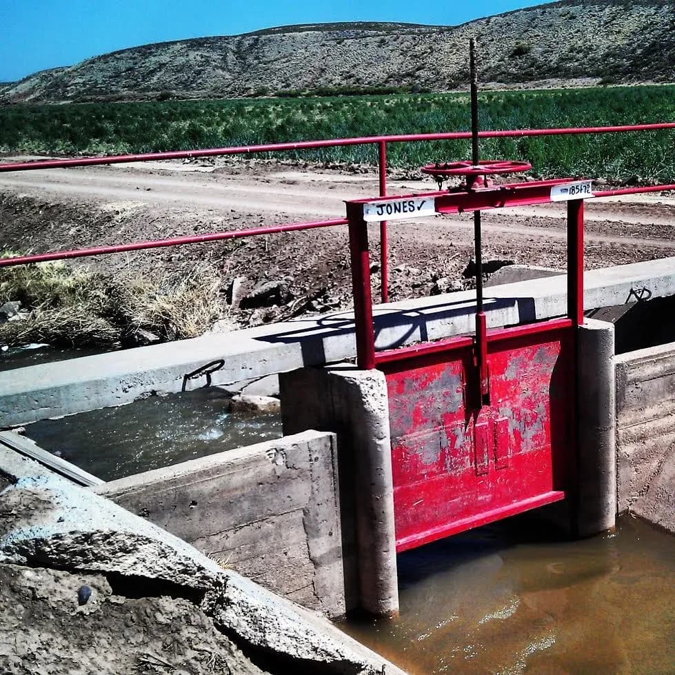
A handwheel-operated irrigation canal gate with a threaded stem in New Mexico. This is a canal gate, not the rotary pipeline valve or motorized assembly in the examples. Photo: Jessica M. Driscoll, USGS; public domain.
For a useful comparison, specify the same isolation duty for both options. Then examine the complete valve, drive, controller, power supply and local operating arrangement. The original torque and energy examples below are hypothetical screening exercises, not IrriNex product ratings or results from a farm installation.
1. Define the job before choosing how the valve moves
Record where the valve sits, which pipe section it isolates, the expected pressure on each side, required flow capacity and how often it must move. Distinguish occasional seasonal isolation from repeated zone switching or intermediate-position control. A valve suitable for full opening and closing may not be qualified for frequent modulation.
A manual handle or handwheel requires a person at the equipment. It can be appropriate when operation is infrequent, access is dependable and a trained operator can meet the required response time. Include the physical effort, turning clearance, weather, route condition and local identification in that assessment. A simple valve can still be difficult to operate when buried behind pipework or reached only by an unreliable track.
A motorized actuator can move a valve through an approved controller interface. Specify whether it is an on-off drive or a positioning drive, the permitted stroke frequency and the required travel time. Remote commands also require a working communication path and control system; these are separate components of the installation.
The U.S. Department of Energy's actuator handbook, pages 54–60, distinguishes motor drives, solenoids and fluid-powered actuators. Its motor example uses gearing, a manual operating arrangement and position or torque limits. Designs vary, so those features must be confirmed on the proposed unit.
A solenoid-operated irrigation valve is not simply another name for a motorized valve. A solenoid may control a pilot passage while water pressure moves the main closure element. A compatible latching arrangement can be another option for a remote zone, but its electrical and hydraulic requirements still apply. Use the irrigation controller compatibility guide for that interface decision.
2. Match torque, travel and the complete mechanical connection
For a rotary valve, request the required operating torque over the relevant stroke and conditions, including initial breakaway, running and final seating where applicable. For a rising-stem arrangement, obtain the required thrust and travel as well as the actuator's relevant ratings. A torque value at the motor shaft is not the same as the delivered torque after the gearbox.
Keep the design conditions attached to the requirement: differential pressure, temperature, seating arrangement, service condition and permitted direction of flow. Also identify the maximum load the stem, coupling, bracket and valve can tolerate. An actuator must provide sufficient useful output without exposing another part to an unacceptable load.
Consider an invented rotary-valve example. Assume the project has established a maximum required torque of 36 N·m and independently chosen a 25% selection allowance. The resulting minimum is 36 × 1.25 = 45 N·m. Assume the complete valve-and-mounting arrangement permits no more than 70 N·m of transmitted torque. Neither the allowance nor either torque limit is a universal irrigation rule.
| Candidate | Documented minimum available output | Documented maximum transmitted torque | Screening result |
|---|---|---|---|
| A | 42 N·m | 60 N·m | Below the 45 N·m minimum requirement |
| B | 50 N·m | 68 N·m | Meets these two torque inequalities; other checks remain |
| C | 65 N·m | 90 N·m | Exceeds the 70 N·m transmitted-load limit |
For this exercise, the listed limits are assumed to have been established for each complete proposed configuration across the required supply and temperature conditions. They are not just nameplate values measured under different conditions. Candidate B passes only this torque screen; the table does not approve its hydraulic duty, travel, coupling, enclosure or control behavior.
Do not select an oversized drive and casually raise or alter torque settings to force a reluctant valve. Ask the valve and actuator suppliers to document the approved combination, protective settings and verification procedure. A torque interruption may indicate that movement stopped before the requested endpoint; it is not itself confirmation of successful closure.
3. Check available output where the actuator actually operates
Identify the supply type, permitted voltage range at the actuator terminals, starting demand, running demand and any separate control supply. Long field cables, connections and simultaneous loads belong in the electrical design. A nominal battery voltage at the enclosure does not establish the voltage available at the motor while it is moving.
NRC-sponsored motor and gearbox research, NUREG/CR-6478, tested industrial actuators under load, reduced voltage and elevated temperature. Its results show why nominal ratings and simplified correction methods need careful interpretation. These were specific industrial test specimens, not agricultural valve qualification results; their numerical correction factors should not be transferred to a farm actuator.
For the proposed installation, request the supported output and stroke time at the actual limiting conditions. Distinguish a brief high starting demand from average running power. Check the drive electronics, protective devices, cable and source against their own requirements; enough stored watt-hours does not prove that the system can start or finish a stroke.
Duty limits also matter. Twenty 30-second strokes total 600 seconds, or 10 minutes of movement in a day. That average says nothing about whether the same strokes are permitted in a short burst, whether rest periods are required, or how many starts the drive allows. Compare the intended sequence with the selected equipment's actual duty definition.
4. Budget movement and standby energy separately
Suppose a hypothetical remote station uses a regulated 24 V DC load bus. Assume its actuator draws a constant 2 A during each 30-second stroke, makes 20 strokes daily, and draws no power between strokes. Twenty strokes here mean 10 complete open-and-close pairs. These assumptions are only for arithmetic; real current and duration should come from suitable operating data.
Motor power in the example is 24 × 2 = 48 W. One stroke consumes 48 × 30 ÷ 3,600 = 0.4 Wh, and 20 strokes consume 8 Wh daily. Now include two separate continuous loads: 0.20 W for control electronics and 1 W for communications. These loads are additional to the stated motor power, including while the motor moves, so they have not already been counted.
| Load | Calculation | Daily energy |
|---|---|---|
| Actuator movement | 48 W × 30 s × 20 ÷ 3,600 | 8 Wh |
| Separate control electronics | 0.20 W × 24 h | 4.8 Wh |
| Separate communications equipment | 1 W × 24 h | 24 Wh |
| Total | 8 + 4.8 + 24 | 36.8 Wh |
For an assumed 3-day period without recharge, the loads require 36.8 × 3 = 110.4 Wh. Consider an illustrative battery labeled 24 V, 10 Ah: its nominal arithmetic energy is 240 Wh. If only 50% is allocated as usable stored energy and the subsequent delivery path is assumed 85% efficient, the modeled load-bus energy is 240 × 0.50 × 0.85 = 102 Wh. It falls short by 8.4 Wh.
Those two factors are invented, separately defined inputs. They are not universal battery limits or a complete allowance for cold weather, age, discharge rate, protection cutoff or reserve. Do not apply another efficiency factor for a loss already included. The simplified comparison also leaves charging, solar-resource variation and peak-current capability unresolved.
The example reveals a useful procurement question: what does the whole remote station consume while waiting? Communications uses more daily energy here than valve movement. A different reporting interval or device might change that balance, but obtain its actual average and peak loads before claiming a longer autonomy period.
Keep the irrigation automation cost model alongside the electrical assessment. Battery service, recharge equipment and fault-response visits belong in the operating comparison even when the valve itself draws little energy.
5. Specify the response to each interruption
Write a required-state table for the actual installation. The safest response depends on the water source, downstream equipment, injection system and intended isolation duty. A spring, stored electrical energy or another approved arrangement may provide a specified return action, but the capability must be documented for the complete assembly and required load.
| Event | Required evidence | Operator information |
|---|---|---|
| Remote link unavailable | Which local commands or schedule remain authorized | Last trustworthy position and time of lost contact |
| Actuator power lost during travel | Documented final behavior and any reserved return energy | Uncertain position or confirmed final state, as actually supported |
| Movement blocked or drive protection trips | Response without repeated uncontrolled attempts | Trip condition and whether the requested endpoint was reached |
| Local manual control selected | How remote movement is inhibited or coordinated | Local mode, responsible operator and restoration procedure |
| Power or communication returns | Approved recovery and handling of pending commands | Current mode, position and next permitted operation |
Do not infer fail-closed behavior merely because a motorized valve can close normally. Equally, a manually operated valve is not an automatic emergency response just because it needs no electricity. Evaluate who can reach it within the required time and what independent protections are necessary for the system.
The guide to irrigation control with unreliable internet covers local execution and recovery in detail. Here the additional question is whether the selected actuator has the mechanical and energy capability to perform the required action. Connectivity and motion must both be available where the response depends on them.
6. Distinguish a command from position and water isolation
A controller acknowledgment can confirm receipt of a command without proving movement. A position switch can provide evidence that its configured point has been reached, while a position transmitter can describe travel within its verified range. Neither alone proves that the valve seat stops water to the required leakage criterion.
Specify which indications come from commands, drive status, physical position and hydraulic measurements. Identify the sensing point and its relationship to the closure element. If the coupling or feedback arrangement changes during maintenance, repeat the relevant verification instead of relying on the previous display calibration.
For commissioning, record the starting state, command, motion response, final indication and observed hydraulic result under an approved procedure. Keep elapsed travel time distinct from the time needed for downstream delivery to stop. Where flow measurement is used, its range and uncertainty must suit the observation. A meter that cannot resolve small flow cannot establish zero leakage.
Preserve the pump and valve interlocks described in the irrigation automation interlock guide. Adding remote actuation should not allow a pump or injection sequence to proceed solely because a command was transmitted.
7. Make local operation and maintenance practical
Confirm whether the actuator has a manual operating facility, what power isolation or mode selection it requires, and whether its handwheel or lever can move during powered operation. Use the exact manufacturer's procedure with trained personnel. Do not assume that engaging a clutch or turning a wheel is safe while a remote start remains possible.
Provide access for the required tool and hand movement, a readable local valve identifier and a way to determine operating mode. Choose environmental protection for the actual exposure, including possible flooding, condensation, heat, dirt and cable entry conditions. A general weather-resistant description does not establish suitability for continuous submersion or every enclosure temperature.
Complete the comparison with a defined acceptance record: exact valve and actuator references, approved mounting, output and duty limits, power budget, required fault responses, feedback checks and local service instructions. Demonstrate the agreed operating cases under supervision. Retain unresolved items instead of treating a successful unloaded demonstration as proof of the installed duty.
8. Questions about manual and motorized irrigation valves
Is a motorized valve always better for a distant irrigation block?
No. Compare the required response and operating frequency with travel access, mechanical duty, power, communications and service support. An infrequently operated isolation valve may remain practical manually; repeated or time-critical operation needs a different assessment.
Will a motorized irrigation valve close when its battery is exhausted?
Only if the complete installed arrangement provides and retains the required return capability under that condition. Confirm the documented behavior and test method. Normal powered closure does not establish the response to loss of power.
Can I size the battery from the actuator's running current alone?
No. Include stroke duration and count, all waiting loads, available storage under the intended conditions, conversion losses, required reserve and recharge availability. Check starting and peak-current capability separately from the daily energy calculation.