Irrigation Valve Boxes: Plan Drainage, Access, and Cable Connections
An irrigation valve box should keep a valve accessible, protect the installation from the expected surface loads, and accommodate the site's wet conditions without transferring box loads to the pipework. Size it for operation and maintenance, not just the outside dimensions of the valve. Cable connections also need their own suitable environmental protection; a lid does not make the space beneath it dry.
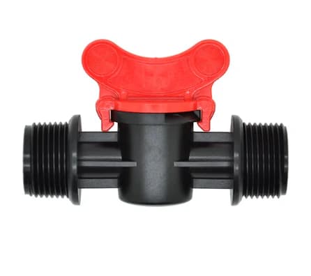
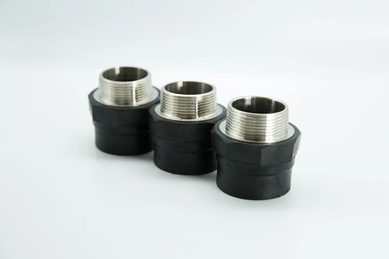
Irrigation fittings with black bodies and metal external threaded ends. Connection geometry is one input to planning maintenance access; this photograph does not show a valve-box installation. Photo: IrriNex.
For agricultural drip and sprinkler zones, start with the tasks the operator must perform: identify the valve, isolate its water supply, reach the controls, disconnect permitted service joints and inspect wiring. This guide develops an access worksheet, a simple drainage-volume example and a handover record for that decision.
1. Choose the location around farm traffic and water movement
Mark the proposed box on the irrigation drawing and inspect the actual field position. Include wheel tracks, cultivation routes, headlands, harvest operations and areas where surface runoff collects. A location convenient during installation can become obstructed by crop growth or regularly crossed by loaded equipment.
Identify the loads the lid, frame and supporting installation must withstand. A label such as heavy duty is not a substitute for a documented load classification and installation detail. The relevant loading includes the contact conditions and support arrangement, not simply the total mass of a tractor mentioned in a catalogue.
Set the finished relationship to soil, mulch or paving according to the chosen installation and operating requirements. Avoid creating a trip point, exposing a lid to routine implement strikes or directing runoff into the opening. Where the surface level changes seasonally, plan how the box remains identifiable and accessible.
The irrigation valve types guide helps establish the equipment schedule. Locate any required isolation and service points as part of that schedule. A covered zone valve should not become unreachable when the crop or surrounding pipework is in place.
2. Define the service envelope before selecting a box size
Tweed Shire Council's irrigation assets specification, section 77, calls for space to operate valves and perform maintenance, supported installation and identifiable lids. It is a public-open-space specification dated January 2018. Its named products and local construction details are not universal farm requirements; the useful planning principle is to make service access an explicit design input.
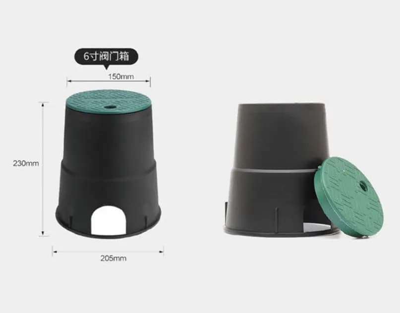
Measure the usable chamber at the equipment elevation, the clear opening after removing the lid, and the vertical access above the service component. These can be different dimensions. Tapered walls, ribs, pipe cutouts and an extension frame can reduce the space available where hands and tools actually work.
For an original hypothetical example, an assembly occupies 380 × 160 mm in plan. Suppose a task review assigns 100 mm of working allowance at each end and 80 mm at each side. The resulting plan envelope is 380 + 2 × 100 = 580 mm long and 160 + 2 × 80 = 320 mm wide. These allowances are invented inputs for the example, not minimum clearances for every valve.
| Check | Assumed requirement | Candidate box measurement | Result of this limited screen |
|---|---|---|---|
| Working space at assembly elevation | 580 × 320 mm | 620 × 400 mm usable | Plan dimensions fit; reach and tools still require a practical check |
| Lift the disconnected assembly straight out, parallel to its installed orientation | 380 × 160 mm passage | 360 × 260 mm clear lid opening | Length fails the specified straight-lift task |
| Alternative clear opening for the same straight lift | 380 × 160 mm passage | 420 × 280 mm | Passage dimensions fit; confirm the entire lifting path |
| Remove the upper service component | Its documented removal stroke plus required tool access | Not yet measured | Unresolved; plan dimensions alone are insufficient |
The straight-lift row explicitly assumes no tilting or diagonal removal in the planned procedure. Another documented procedure could change that requirement. Do not declare a box universally unsuitable from one invented removal method, but do not assume a technician can improvise a different method around fixed pipes either.
Build a dry mockup using the intended assembly and tools before final placement. Check hand access, fastener removal, manual controls and permitted disconnection points. Include the space occupied by wire loops and connectors. The service envelope is the space needed to do the work, not merely an empty rectangle around the valve.
3. Treat drainage as an inflow-and-outflow problem
Water can enter from rainfall, runoff, a pipe leak, adjacent irrigation or groundwater. Establish which route is responsible before changing the base. A box that fills only when a particular zone runs needs a different investigation from one that fills after rain while the irrigation supply is isolated.
Gravel can provide void space and facilitate movement toward a suitable receiving layer or outlet. It cannot make water disappear. In slowly draining soil or a high water table, an excavated pocket of aggregate may remain wet. Determine where water can leave and whether that route remains available during the conditions that cause the problem.
Consider an invented aggregate layer with plan area 0.40 m², depth 0.15 m and an assumed initially empty, accessible void fraction of 0.30. Its idealised available storage is 0.40 × 0.15 × 0.30 = 0.018 m³, or 18 L. This is a volume calculation, not a specified aggregate grading or measured infiltration capacity.
If hypothetical inflow remains 5 L/min and outflow remains 1 L/min, water accumulates at 4 L/min. The 18 L void storage would fill in 18 ÷ 4 = 4.5 minutes under those assumptions. If outflow were zero, the corresponding time would be 18 ÷ 5 = 3.6 minutes. Adding storage delays accumulation; it does not provide a continuing outlet.
These simple times do not predict the flood depth in a real valve box. Antecedent moisture, changing inflow, groundwater, sediment and the actual available pore space change the result. Use site observations and an appropriate drainage assessment before choosing relocation, grading, an outlet or another engineered arrangement.
Any drain needs a suitable destination, maintained hydraulic fall where gravity drainage is intended, and compliance with relevant discharge requirements. Do not connect a valve pit indiscriminately to a water-supply line or an unknown drain. Soil-entry protection and drainage provisions must work together without obstructing the intended water path.
4. Support the enclosure and pipework for their separate loads
The lid and enclosure need the support prescribed for their installation. The pipe, valve and joints need their own suitable support and restraint. Do not allow a settling box edge or an improvised packing piece to load a pipe connection simply because it makes the lid sit at the desired level.
Check pipe-entry clearance with the box in its final supported position. Sharp cutouts should not press against pipe or cable. Include the movement expected from settlement and temperature where relevant. An installation that looks clear before backfilling can become a contact point after the enclosure or surrounding soil moves.
Retain the intended pipe alignment when installing an extension or larger box. Pulling a manifold sideways to fit a wall opening introduces a different load at the fittings. Use compatible components and an installation detail that accommodates the actual geometry. The PVC pipe-size and dimension guide supports checking the physical interfaces.
Locate isolation and depressurization provisions so service can follow the equipment's procedure. A removable lid is not isolation, and a controller's off command is not proof that a line is depressurized. Keep any special equipment access or ventilation requirements in its own approved arrangement rather than enclosing every device under the same generic detail.
5. Specify cable connections for the actual wet environment
Western Washington University's irrigation-system standards call for watertight splices, accessible approved splice locations and identification on record drawings. These are institutional specifications with their own equipment choices. They illustrate why connection protection and traceability need explicit requirements; their wire colours, gauge rules and box dimensions should not be copied as a universal agricultural design.
Select a complete connection system suitable for the conductor material, wire count, sizes, voltage and expected environment. Where direct burial or submersion can occur, verify the corresponding stated suitability and installation conditions. “Weatherproof” on a package does not by itself answer every exposure question.
Position and secure connectors so they remain accessible, are not pinched by the lid and do not obstruct service. Keeping them above routine sediment can help inspection, but location alone does not replace the required environmental rating. Plan for the actual wet condition rather than relying on the hope that a box will never fill.
Provide the service slack required by the equipment and installation procedure, respecting cable bend limits. Enough spare length can allow a connection to be inspected without pulling on a solenoid lead. Excess loose cable that tangles around the valve or is trapped by the cover creates another problem; retain and label it deliberately.
Follow the connector's specified stripping, preparation, sealing and closure instructions. Do not improvise sealing by adding an arbitrary grease or shortening wires until an unsuitable cap appears to grip. The controller station-and-common wiring guide covers the separate circuit-identification task. Lead colour or a click at the solenoid cannot verify the completed hydraulic operation.
6. Diagnose a wet or inaccessible box with a short evidence record
Record when the problem occurs and what the surrounding system is doing. Photograph the equipment and water level before disturbing the arrangement, where safe. Note recent rain, irrigation states, visible inlet paths, soil movement and whether the location was previously modified.
| Observed pattern | Possible route to investigate | Useful next evidence |
|---|---|---|
| Water appears during a particular irrigation event | Pipe or fitting leak, or irrigation entering from outside | Timing, visible flow path and the affected zone's operating condition |
| Water rises after rain with irrigation isolated | Surface runoff, saturated soil or groundwater | Surrounding levels and how the water level changes afterward |
| Dry-weather water persists near a pressurised main | Supply-side leakage or another continuing inflow | An authorised isolation and inspection assessment |
| The lid settles or a pipe touches the enclosure | Support or backfill movement | Final bearing condition, clearances and pipe alignment |
| Manual controls or connectors cannot be reached | Insufficient working space or obstructed service route | A task-specific access check with the intended tools |
These patterns narrow the investigation; they are not diagnoses from one observation. A box can have more than one inflow source, and a wet connection may coexist with a mechanical valve fault. The electrical-versus-hydraulic valve troubleshooting guide helps keep those fault paths separate.
Use the appropriate isolation and safe-work procedure before intrusive inspection. Do not loosen a pressurized fitting or probe damaged electrical connections while standing in accumulated water. Correct the source of the problem and the affected equipment condition; merely removing visible water does not verify the installation.
7. Hand over a layout that the next technician can use
Give the box, valve and controller station consistent identifiers and record their relationship. Retain a location reference that remains useful when crops, surface cover or landmarks change. If a cable splice is in a separate enclosure, include it on the same drawing and connection record.
| Record | What to include | Acceptance question |
|---|---|---|
| Location and surface loading | Drawing reference, operating access and specified lid/support arrangement | Can the location tolerate the expected farm use? |
| Service access | Usable dimensions, removal path and completed tool-access check | Can the required maintenance tasks be performed? |
| Water management | Observed inflow routes, receiving soil or outlet, and inspection needs | Is there a documented response to the site's wet conditions? |
| Cables and identification | Connector specification, wire labels, retained slack and splice locations | Can connections be traced and serviced in their expected environment? |
Check the arrangement again after final backfilling and surface work. Confirm that the lid opens, the identification is readable, the intended clearances remain and the valve performs its required function under the agreed test conditions. Record anything not yet demonstrated instead of treating a closed lid as completion.
8. Questions about agricultural irrigation valve boxes
Will a gravel base keep an irrigation valve box dry?
Only if the complete site arrangement can move incoming water to an adequate receiving layer or outlet. Gravel provides finite void space; it cannot compensate indefinitely for greater inflow than outflow or a high groundwater level.
Can I choose a box just by the valve's pipe size?
No. Assembly dimensions, tools, controls, cable connections and component-removal paths determine the required space. Check the usable chamber and lid opening separately with the intended maintenance procedure.
Are ordinary wire connectors adequate under a valve-box lid?
Use a connection system with the stated suitability for the conductors and actual exposure. A covered below-ground space can still be wet or submerged. Positioning and slack help access but do not replace the required connector protection.