Irrigation Pump Soft Starters vs Variable-Frequency Drives: Match the Control Duty
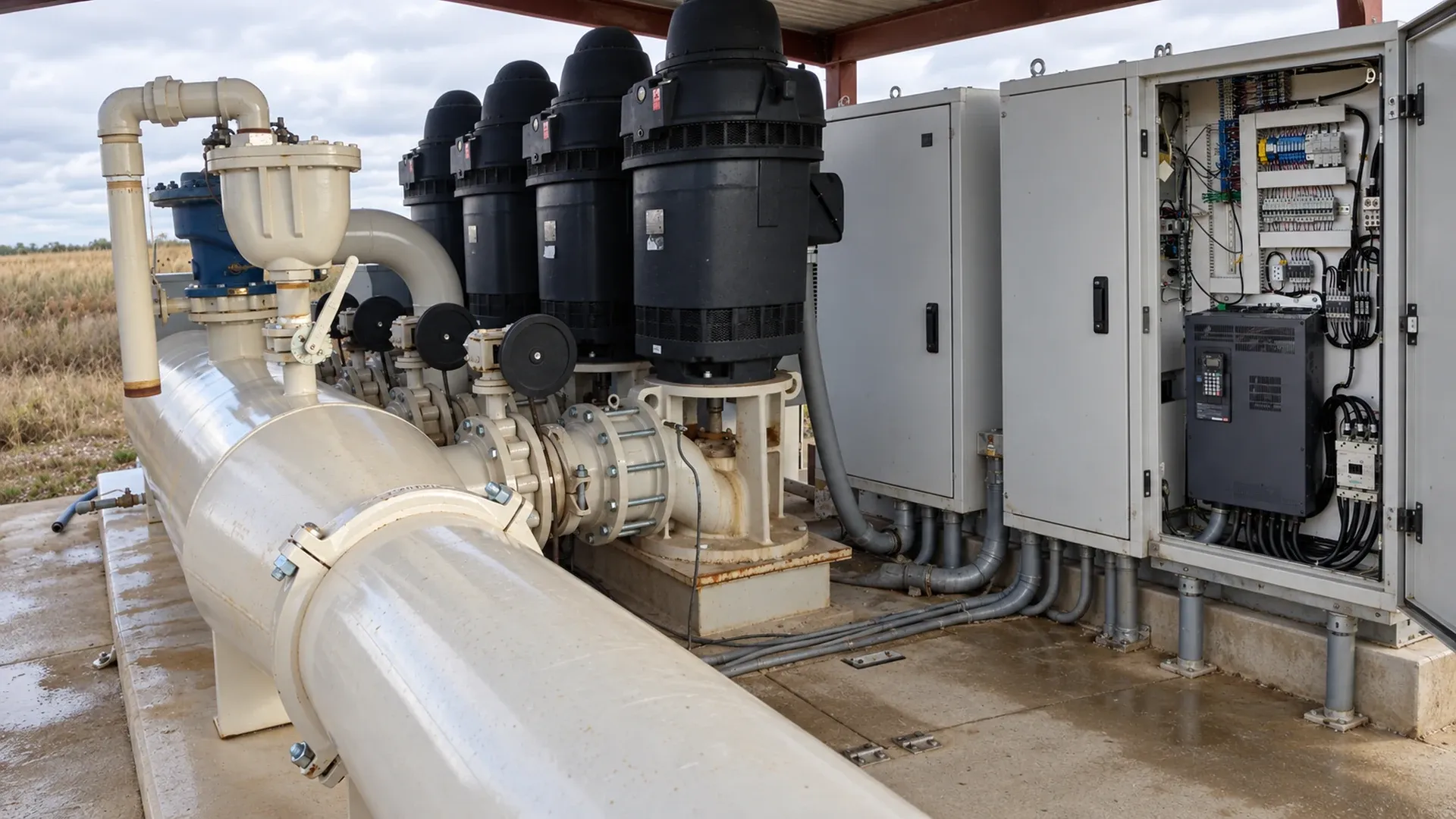
A soft starter is a candidate when an irrigation pump will run at essentially one speed and the main problem occurs during starting. A variable-frequency drive (VFD) is a candidate when the required flow, pressure or operating setpoint changes while the pump runs. That distinction starts the selection process; the motor, electrical supply and hydraulic system must still pass a joint engineering review.
Good pump station control begins with a written duty profile. Buying a drive because it can start gently does not establish a need for continuous speed control. Equally, fitting a soft starter to a pump serving very different irrigation demands does not correct excessive running pressure. This guide gives a comparison, a three-duty example and an acceptance record for discussing the installation with qualified pump and electrical specialists.
1. Separate the starting event from the operating duty
A reduced-voltage soft starter controls applied voltage during motor acceleration, influencing starting current and torque. It does not independently vary the supply frequency to regulate running speed. Many arrangements transfer to a bypass contactor after acceleration, leaving the motor operating from the line at its normal loaded speed. Some provide controlled stopping; that feature must be evaluated separately from continuous speed regulation.
A VFD converts incoming electrical power and controls motor frequency and voltage. It can adjust speed throughout operation, within approved motor and pump limits. A pressure or flow control loop then changes the speed command in response to a measured variable. A VFD without a suitable sensor, control strategy and operating envelope is not automatically a constant-pressure installation.
Utah State University Extension's irrigation VFD guidance distinguishes variable operating demand from a need for soft starting alone. Its purchasing review also emphasizes current rating, site conditions and field-specific economics. The worksheets below turn that selection question into information that an installer can evaluate.
2. Compare the control functions before comparing prices
| Review item | Soft starter | VFD |
|---|---|---|
| Starting current and acceleration | Controls the start, subject to available torque and thermal limits. | Controls acceleration through frequency and voltage; supply capacity still matters. |
| Steady running speed | Normally fixed by supply frequency and motor load. | Adjustable within an approved speed range. |
| Pressure or flow regulation | Requires other hydraulic or system controls during full-speed running. | Can regulate through speed when feedback and the hydraulic design support it. |
| Sensors and logic | Start permissives and protective signals remain necessary. | Adds feedback scaling, loop tuning, limits and sensor-failure behavior. |
| Energy opportunity | No inherent reduction in full-speed pumping head after bypass. | Depends on the actual duty distribution, efficiencies and avoidable head. |
| Harmonics and EMC | Assess starting disturbance; bypass changes the running condition. | Assess ongoing input harmonics and electromagnetic compatibility. |
| Motor insulation and cables | Verify compatibility with the starting duty. | Review inverter output, insulation, cable length and required output treatment. |
| Motor cooling | Repeated starts and long acceleration can cause heating. | Low-speed cooling and continuous load require explicit approval. |
| Bypass arrangement | Often used after the starting ramp. | An optional line bypass gives fixed-speed operation and needs a separate safe duty. |
| Enclosure environment | Check start frequency, heat rejection, dust and moisture. | Account for continuous electronics losses and cooling maintenance. |
| Service and complexity | Usually fewer control functions to maintain. | Needs support for parameters, sensors, communications and drive replacement. |
Neither device replaces overcurrent protection, an isolation procedure or a pump protection strategy. A bypass contactor is an operating component, not proof of safe electrical isolation. A drive's displayed current is useful information, but it does not establish adequate suction water or acceptable pressure at the farthest irrigator.
3. Write a farm duty profile that describes real irrigation
List each allowed zone combination, pivot position or end-gun state. Record the required flow, the minimum pressure at the hydraulically critical outlet, the static elevation component and the water-source condition. Add annual operating hours, starts per hour or day, the duration of each run and the combinations that must never occur. Include filter-cleaning demand and valve transitions when they change the pump duty.
Use one row per meaningful condition. An annual average flow conceals both short high-demand periods and long small-zone runs. Identify where each pressure is measured: suction, discharge header and remote outlet are different locations. Keep the pump differential head separate from an outlet pressure setpoint. The flow and total dynamic head sizing method explains the pressure budget needed before controls are selected.
For each row, distinguish a measurement from a design assumption. Date the source-level readings and note whether the filters were clean. A wet-season test may not describe late-season lift. Ask the irrigation manager to sign off the permitted combinations; otherwise an electrically sound controller can repeatedly command a hydraulic duty the station was never designed to deliver.
4. Worked example: one pump, three operating points
Consider a hypothetical farm with three permitted duties. The flows below are US gallons per minute, with rounded SI equivalents. The critical pressure is required at the remote outlet, not at the pump flange. Hours are illustrative planning inputs, not measured performance or an energy-saving claim.
| Allowed duty | Required flow | Critical outlet pressure | Annual hours |
|---|---|---|---|
| Large zone combination | 600 gpm ≈ 136 m³/h | 45 psi ≈ 310 kPa | 800 h |
| Medium zone combination | 450 gpm ≈ 102 m³/h | 40 psi ≈ 276 kPa | 600 h |
| Small zone combination | 300 gpm ≈ 68 m³/h | 35 psi ≈ 241 kPa | 400 h |
Suppose the highest outlet is 40 ft, approximately 12.2 m, above the source water surface. At the 600 gpm duty, assume pipe and equipment losses of 20 ft, approximately 6.1 m. For this simplified open-source example, total head is about 40 + 20 + (45 × 2.31) = 164 ft, or 50 m of water. Actual evaluation must account consistently for measurement elevations, inlet conditions and velocity terms.
At 450 and 300 gpm, calculate losses for the actual active routes and source level. Do not assign the same 20 ft loss to every condition, or simply multiply the complete 164 ft head by the flow ratio. Static lift remains even when friction falls. A changed zone route may have a different elevation and pipe length.
If the sole complaint is harsh starting before a long, stable 600 gpm run, a suitable soft starter may satisfy the control task. If the farm spends 1,000 hours in the two smaller duties, assess a VFD against all three pump/system intersections. A soft starter still leaves the pump on its full-speed curve after acceleration; it cannot select a new steady running speed for the smaller demand.
For an energy comparison, use annual energy = Σ(measured electrical input kW at duty i × hours at duty i). The three rows total 1,800 operating hours. Compare equivalent delivered water and outlet pressure, include drive and cooling consumption, and use the applicable tariff. Without input-power measurements or a defensible efficiency model, this worksheet supports a selection study, not a savings percentage.
5. Keep every speed inside the pump and motor envelope
For the same centrifugal pump geometry, affinity relationships are useful screening approximations: Q₂/Q₁ ≈ N₂/N₁ and H₂/H₁ ≈ (N₂/N₁)² at corresponding points. The familiar cubic power relationship also assumes comparable efficiency. These are not instructions to halve speed when the requested flow halves. The actual flow occurs where the speed-specific pump curve meets the active system curve.
Check the proposed minimum and maximum speed against the supplier's allowable operating region, minimum continuous flow, required head, shaft or bearing restrictions and motor cooling. Verify available versus required net positive suction head (NPSH), with the specified margin, at the relevant source levels. Reduced speed does not repair an air leak, blocked inlet or inadequate submergence.
A high static lift can leave little useful turndown before the pump cannot open the check valve or deliver water. At the other extreme, a speed increase may exceed motor current or downstream pressure limits. Plot the duties using pump and system curves for changing zones; accept only the range that satisfies both water delivery and equipment limits.
6. Review the electrical source and installation conditions
Give the electrical specialist a complete load description
Provide motor nameplate current, voltage, frequency, service factor and motor history, together with actual operating current and the proposed starting duty. Include starts per hour, acceleration duration, transformer or generator capacity, other loads, voltage and phase balance, available fault level and utility requirements. A reduced-current start still needs enough torque to accelerate the pump within approved thermal limits.
Drive selection must use the required output current and the manufacturer's applicable ratings, with derating for temperature, altitude and load conditions. Horsepower alone is insufficient. Motor condition, insulation compatibility, motor lead length and low-speed cooling also require review. A service factor is not permission to assume unlimited overload, and a drive should not hide an already overloaded pump.
Coordinate protection, power quality and cooling
The qualified designer should determine whether a harmonic study, input reactor, output filter or other treatment is needed. Assess electromagnetic interference with sensor and communication circuits, surge and lightning exposure, grounding arrangements and the enclosure environment. Dust, condensation, insects, direct sun and restricted ventilation can make a nominal enclosure rating an incomplete description of the installation.
Do not choose cable, fuse, breaker, harmonic limits or protection settings from a generic article. Those decisions belong to the drive and motor suppliers and qualified electrical personnel under local requirements. Inspection inside a panel, energized testing and protection adjustments require the applicable authorization and procedures. Isolation, lockout and tagout must address stored energy as well as the supply.
7. Check the water transient separately from the electrical ramp
A smooth motor acceleration does not prove a safe hydraulic start. Record how pressure rises, when the check valve opens and whether the line is initially full or partly drained. At stopping, deceleration can interact with reverse flow, check-valve closure and air admission. Long pipelines or large elevation changes may require a transient analysis covering water hammer and column separation.
Coordinate pump commands with valve opening, closing and filling sequences. The relevant question is whether the permitted water path exists before flow is established and remains suitable while flow falls. Review the operating roles of irrigation valves when separating isolation, regulation, check and air-valve functions.
Review a normal stop, a power failure, a drive trip and a restart as different events. An electrical supply failure may remove the ability to execute a programmed stopping ramp. Document pressure limits and allowed restart conditions for each event. Repeatedly resetting a trip without finding its cause can turn a recoverable control fault into a pump or pipeline failure.
8. Commission against a written acceptance record
| Test group | Record | Acceptance basis |
|---|---|---|
| Baseline | Source level, valve state, full-speed flow, differential head and input power. | Agreed reference duty and calibrated instruments. |
| Start and speed | Commanded and measured speed, acceleration time and starts. | Approved motor and starter or drive duty. |
| Electrical loading | Phase voltages and currents, with measurement method. | Qualified review of load, balance and supply limits. |
| Each allowed irrigation duty | Flow, header and critical pressure, head and stable speed. | Required delivery inside the pump envelope. |
| Feedback | Sensor location, range, calibration and loss-of-signal response. | Correct scaling and an approved failure state. |
| Thermal and mechanical behavior | Motor and panel temperatures, vibration and noise. | Supplier limits under representative operating conditions. |
| Transitions and trips | Pressure rise/fall, check-valve response and restart inhibition. | Transient assessment and authorized restart sequence. |
| Handover | Fault history, final parameters, setpoint limits and service contacts. | Traceable settings and an identified responsible person. |
Use a flow measurement method suitable for the installation; the flow-meter pulse conversion guide helps prevent incorrect totals when pulses enter the controller. A displayed flow value should agree with its configured units and an independent check.
Test the smallest permitted duty as deliberately as the largest. Observe settled operation, a change between duties and the approved response to feedback loss. The pump and valve interlock method provides the demand-permissive logic that either starting technology still needs. Record remaining exceptions before accepting unattended operation.
9. Use symptoms to choose the next review
| Observed symptom | Possible review area | Required response |
|---|---|---|
| Long acceleration or thermal trip | Available torque, loaded start, voltage or excessive starting frequency. | Preserve the event record; have the approved starting duty reassessed. |
| Current imbalance | Supply, motor condition or measurement quality. | Refer measurements and loading history to qualified electrical personnel. |
| High pressure after soft-start bypass | Full-speed pump duty exceeds the active zone requirement. | Review the operating point and pressure-control strategy. |
| VFD pressure hunting | Sensor location, scaling, control response or changing valves. | Check hydraulic records and have the control loop reviewed. |
| Motor heating at low speed | Insufficient cooling or unsuitable continuous load. | Return the speed envelope to the motor and pump suppliers. |
| Harmonic or interference complaints | Supply distortion or electromagnetic coupling. | Request a site power-quality and compatibility assessment. |
| Trips following lightning | Surge damage or compromised protection. | Keep the fault record and obtain an authorized inspection. |
| Check-valve slam | Flow reversal, closure dynamics or an unsuitable stopping sequence. | Reassess the transient and valve selection. |
| Failed or implausible sensor signal | Sensor, connection, scaling or communication fault. | Use the approved safe response; prohibit uncontrolled speed escalation. |
These symptoms are prompts for diagnosis, not proof of a single failed component. Record the duty, time, weather, source level and recent changes with each alarm. A low-pressure complaint can be caused by a partly closed valve or source shortage; increasing speed may worsen the underlying problem.
10. Compare the complete ownership cost
Request separate figures for equipment, electrical and hydraulic studies, installation, enclosure cooling, sensors, integration and commissioning. Add maintenance, replacement availability, software or communication support where applicable, service travel and the cost of interrupted irrigation. Evaluate operating energy against the measured duty hours, including any effect of tariffs and demand charges.
A simpler soft starter can be the appropriate purchase for a stable duty with a starting problem. A VFD may justify additional cost where useful speed changes persist for meaningful hours. Neither conclusion follows from a universal payback period. Compare both with correcting the pump selection or changing allowed zone combinations when those alternatives address the actual problem.
11. Questions to settle before ordering
Can a soft starter maintain constant pressure as zones change?
Not by continuous motor-speed regulation. After acceleration, a conventional soft starter leaves the pump at essentially fixed speed. Constant pressure would need other controls or a pump arrangement matched to the varying demand.
Does a VFD guarantee lower energy use?
No. The result depends on avoidable head, static lift, operating hours and combined pump, motor and drive efficiency. Compare measured input energy for equivalent irrigation delivery. A drive operating near full speed throughout the season may offer little energy benefit.
Does a longer starting or stopping ramp prevent water hammer?
Not necessarily. The pressure transient depends on pipeline length, elevations, water-column condition and valve behavior. Any proposed ramp must satisfy motor limits and a separate hydraulic assessment, including power-loss events.
What should the farm receive at handover?
A signed duty table, the approved speed or starting limits, measured acceptance results, a parameter backup, clear alarm and restart rules, and a named service contact. Those records show why the chosen control fits the farm and make later changes reviewable.