Irrigation Controller Surge Protection: Coordinate Grounding and Field Wiring
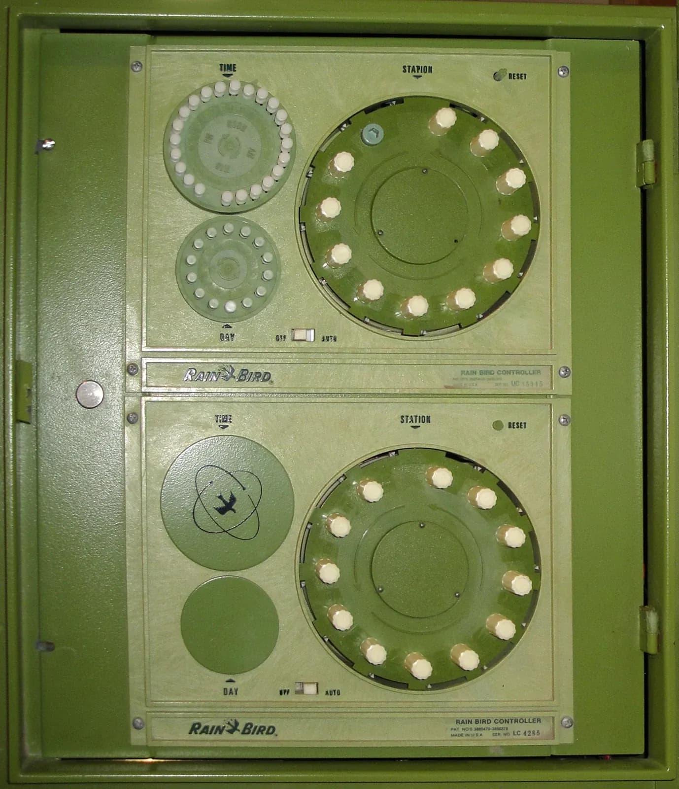
An irrigation controller surge-protection plan must account for the power supply, field wiring and communication connections together. Identify every conductive connection, use protection compatible with that circuit, and have grounding, bonding and installation details coordinated for the complete system. A protector fitted to the mains supply does not by itself establish protection for remote valve and sensor connections.
An older mechanical irrigation controller. This historical equipment photograph does not establish installed surge protection or grounding compliance and does not depict an IrriNex product. Photo: TFNorman, public domain.
This guide produces a review and handover record for agricultural irrigation control equipment. It includes an original inductance illustration, with explicitly hypothetical values. It does not prescribe electrode dimensions, conductor sizes, surge ratings or connections for a particular controller; those depend on its documentation, the installation design and applicable requirements.
1. Separate surge damage from other controller failures
Record what actually happened: loss of display, damaged input, unavailable stations, changed settings, repeated resets or loss of a communication link. Retain the event time, weather observations, supply history and affected equipment. A failure after a storm is a reason to investigate possible surge exposure, not proof of the entry path or the only cause.
A short-duration overvoltage, a sustained supply problem and an outage require different responses. Moisture, loose connections and an overloaded output can also produce controller faults. Separate the initial symptom from the diagnosis so that a replacement controller is not installed into an unresolved electrical problem.
NIST's 2001 guide, Surges Happen!, distinguishes lightning and switching surges from sags and outages. It also explains why equipment connected to both power and another conductive system can experience damaging voltage differences between connections. Its household examples provide background principles here, not current farm installation requirements.
Establish the architecture using the AC, DC and decoder controller guide. Conventional station wiring, a decoder communication-and-power path, and a low-power remote controller require different compatibility checks. Calling all of them irrigation wiring is insufficient for selecting a protective device.
2. Make an interface register before choosing devices
Give each cable or conductive interface an identifier and mark its endpoints on the site drawing. Include the actual route, entry location, connected equipment, circuit function and existing protection. A communication gateway may create an additional path even when it was added after the original irrigation installation.
| Interface | What to identify | Question for the coordinated design |
|---|---|---|
| Incoming electrical supply | Source, voltage system, protective equipment and cabinet entry | What protection and disconnection arrangement applies to this supply? |
| Conventional station and common wires | Output module, remote valves and shared return routes | Which approved arrangement protects these output circuits? |
| Two-wire decoder path | Controller interface, branches, decoders and approved accessories | Will the protection preserve the specified power and communication behavior? |
| Sensor or meter connection | Signal type, supply, cable route and receiving input | What electrical and signal limits must the protective arrangement respect? |
| External communication connection | Copper network cable, antenna connection or other actual interface | Which conductive paths remain, and how are they coordinated? |
Mark unused or absent interfaces as such rather than assuming every cabinet has the same connections. Record both ends of long field cables; reviewing only the controller enclosure can miss equipment at the remote end. The register is a scope document, not a requirement to fit the same protector at every row.
Distinguish a wireless data link from the whole installation being electrically isolated. A radio-equipped device can still have a power cable, antenna connection, sensor leads or valve wiring. Review the actual arrangement using the irrigation connectivity comparison, then retain only the interfaces that exist on site.
3. Match surge protection to normal operation as well as exposure
For each proposed protective device, obtain the exact model, application, installation instructions and relevant ratings. Have the designer check the electrical system, maximum continuous operating conditions, protection modes, applicable transient test ratings and required fault protection. A high energy or surge-current number alone does not establish compatibility with the circuit being protected.
For field outputs, verify that normal valve operation remains supported. For a decoder path, confirm approval for that controller and its signaling system. For a sensor input, check the signal range, permitted loading and any effect on measurement. Connector shape, a familiar nominal voltage or the word industrial on a listing cannot replace these checks.
Record the protected terminals and the reference connections shown in the approved design. Do not substitute a mains device onto a low-voltage signal circuit or add an unapproved suppressor across a solenoid. A modification can change how the output switches, how the valve releases or how a decoder communicates.
Ask what happens when the protective element reaches its service endpoint. Does the connected load remain energized, become disconnected or require a replaceable module? What does the status indication actually mean? NIST's guide notes that protective-device failure can leave equipment powered in some designs, and that indicator meanings need to be retained with the documentation.
4. Coordinate grounding, bonding and the physical route
Use separate labels for protective earth, bonding, the irrigation circuit common and a communication reference. Their functions differ. A common terminal that completes a valve circuit is not automatically a connection for an earth electrode, and a cable shield is not automatically the circuit return.
Have the responsible designer reconcile the controller instructions with the supply, field protection and grounding design. Record the intended bonding arrangement and how separate equipment locations relate to it. Adding an isolated electrode because it is convenient can leave the relationship between conductive systems unresolved; adding an arbitrary bond can also violate the supported circuit arrangement.
Keep the approved connection route visible in the drawing and installation record. The NIST guide's discussion of shifting reference potentials illustrates why separate power and communication protections must be considered together. Its old residential wiring dimensions should not be copied into an agricultural controller installation.
Installation geometry matters during a rapidly changing current. Follow the selected equipment's requirements for connection routing and allowable lead arrangement. Do not introduce unnecessary loops or extensions as an unreviewed field change. At the same time, preserve the specified separation, enclosure access and electrical protection; shortening a route is not permission to bypass another requirement.
5. Understand why a continuity reading cannot prove surge performance
A low-resistance continuity result answers a different question from the voltage produced during a fast current change. Rice University's OpenStax treatment of self-inductance relates induced voltage to inductance and the rate of change of current. For a simple constant-inductance model, the voltage magnitude is L multiplied by the magnitude of dI/dt.
Consider an invented current ramp of 600 A over 3 microseconds. Its rate of change is 200,000,000 A/s. Compare two hypothetical effective inductances under that same ramp. These are model inputs, not measured cable values, controller tests or a proposed lightning test.
| Assumed inductance | Current-change rate | Voltage magnitude from the model |
|---|---|---|
| 0.5 microhenry = 0.0000005 H | 200,000,000 A/s | 100 V |
| 2 microhenries = 0.000002 H | 200,000,000 A/s | 400 V |
The fourfold inductance difference produces a fourfold voltage difference in this simplified comparison. It explains why the connection arrangement deserves attention even when a conductor passes an ordinary continuity check. It does not convert a measured lead length into an inductance or establish the voltage at the controller terminals.
A real surge involves a complete circuit, current paths, mutual coupling, equipment behavior and a waveform. Do not add these example voltages to a protector's label and treat the sum as a validated protection level. Likewise, an electrode-resistance reading by itself is not a test of the complete controller's response to lightning.
6. Commission the documented installation without creating a surge
Use the approved inspection and test plan with suitably qualified personnel. Retain the installed part numbers, connection photographs, route drawings, required test results and instrument details. Confirm that any field variation has been reviewed before accepting the installation. Do not attempt to demonstrate protection by improvising a high-voltage pulse.
Use the controller wiring test-map guide to preserve the identity of circuits and measurement points. Follow the equipment's instructions for isolation and testing. An insulation test intended for a disconnected cable can damage attached electronics if applied to a controller, decoder or protective device without the required separation.
Then verify normal irrigation functions: supported station commands, required valve closure, sensor readings, communication and the documented recovery behavior after an approved supply interruption. Passing an ordinary functional test confirms those observed functions; it is not evidence that the installation survived a specified surge waveform.
| Record | What completion means | What it does not establish |
|---|---|---|
| Interface register and drawing | Actual connections and endpoints are identified | Every interface has the same protection requirement |
| Approved device and installation schedule | Equipment and connection details match the reviewed design | A substituted part is automatically equivalent |
| Required inspection and electrical test results | Specified checks have documented outcomes | Ordinary continuity predicts all transient behavior |
| Irrigation functional record | Observed commands, readings and responses meet the test plan | A surge-withstand rating has been demonstrated on site |
| Status and service instructions | Operators know indications, responsibility and replacement procedure | Power remaining on proves continued protection |
7. Plan inspection and recovery after a storm
Arrange weather monitoring and safe access before the storm season. The National Weather Service's lightning guidance advises immediate safe shelter when thunder is heard and remaining sheltered for at least 30 minutes after the last thunder. Do not walk out to a valve box or open a controller cabinet during a thunderstorm to protect the equipment.
After conditions and the site procedure permit access, retain the event evidence before clearing logs or replacing parts. Have damaged or suspect electrical equipment assessed using the appropriate isolation procedure. Compare supply, field-output, sensor and communication symptoms with the interface register rather than assuming all failed parts share one cause.
Check each protective device's documented status and service requirements. Record any replacement, the reason and the subsequent functional verification. If a protection module has failed, replacing it without reviewing the surrounding installation may leave an unresolved entry path, unsuitable component or installation defect.
The irrigation alarm-design guide helps assign responsibility for abnormal supply, unavailable stations and loss of communication. The operating record should state who decides when watering can resume and how the required water state is confirmed. Remote visibility can support that decision, but cannot replace a required electrical inspection.
8. Questions about irrigation controller surge protection
Does a surge protector on the mains protect every valve wire?
It does not establish protection for every field connection. Review all actual conductive interfaces and the complete grounding and bonding arrangement, using equipment approved for each circuit and its operating requirements.
Can the irrigation common wire be used as an earth connection?
Do not assume that it can. The common is part of the control circuit; protective earth and bonding serve different functions. Use the controller instructions and the coordinated electrical design to identify the required terminals and connections.
Does a working controller mean its surge protection is healthy?
No. Some protective arrangements can leave equipment powered after a protective element fails. Check the actual status indication and service instructions, retain the inspection record and confirm normal irrigation functions after any repair.