Technical2026-11-12
A fertigation system needs protection on two connected paths: the irrigation mainline and the fertilizer injection line. Put the locally accepted source-protection assembly upstream of every injection point, prevent irrigation water from entering the stock tank, and verify that fertilizer flow stops when irrigation flow or control power is lost. The required device combination depends on the water source, material being injected, hydraulic conditions and local approval. A check valve by itself is not proof that the complete installation is protected.
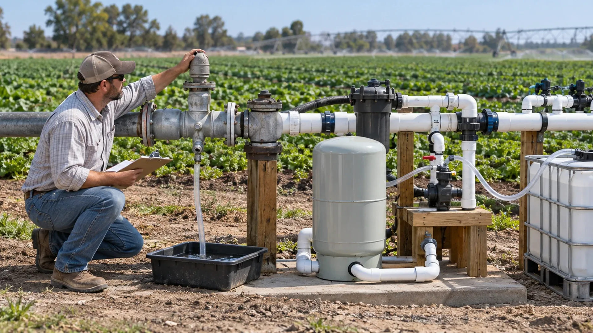
This guide turns those principles into a failure-path review, a selection brief and a commissioning record. It is for growers and irrigation managers preparing a system for review by a qualified designer or tester. The worked example is hypothetical, and the hero image is an AI-edited illustration based on real agricultural equipment photographs, not a certified installation diagram.
Backpressure occurs when pressure downstream of a connection exceeds pressure on its supply side. An elevated field, a pressurized vessel or another pump can provide that pressure after the irrigation pump stops. Backsiphonage occurs when falling supply pressure creates suction that can draw a contaminated mixture toward the source. Both mechanisms matter even if the system operates normally all afternoon.
Also distinguish source contamination from tank contamination. A leaking mainline barrier can send fertilizer toward a well or shared supply. A leaking injection-line barrier can send irrigation water into the fertilizer tank, causing dilution or overflow. Gravity can move stock solution into the mainline even when the dosing motor is off. Trace every branch and bypass before choosing devices.
| Initiating event | Unwanted movement | Protection to verify |
|---|---|---|
| Irrigation pump stops; injector remains enabled | Fertilizer enters a stagnant or draining mainline | Injection shutdown on lost irrigation permission, with positive chemical shutoff |
| Injector stops; mainline stays pressurized | Irrigation water passes backward through the injector into the tank | Injection-line nonreturn function and the specified shutoff arrangement |
| Supply pressure falls sharply | Mixed water is drawn toward the source | Accepted backsiphonage protection, correctly located and unobstructed |
| Elevated pipework or stored pressure discharges | Downstream water pushes toward the pump and source | Accepted backpressure protection under the actual pressure envelope |
| Check-valve seat leaks | Mixture crosses the nominally closed barrier | Seat inspection, prescribed leak test and functional secondary provisions |
| Drain or vacuum-relief opening is blocked | A protective discharge or air-admission path becomes ineffective | Accessible openings, correct discharge routing and approved functional test |
| Stock tank stands above the injection connection | Fertilizer siphons or flows by gravity after shutdown | Anti-siphon capability and positive shutoff appropriate to the stock head |
The mainline and injection-line checks perform different jobs. Use the irrigation valve maintenance checklist for routine inspection planning, then add the device-specific tests and source-protection approval described here. Maintenance cannot turn an unsuitable valve into an accepted backflow assembly.
For a pumped source, a functional review starts with: source → irrigation pump → approved source-protection assembly → injection point → distribution equipment → field. Locate any pressure tank, additional pump, bypass and shared service on the drawing because each can change the pressure on a barrier. A public pressurized supply may have a different approved connection arrangement. The drawing must identify every injection point downstream of the relevant source protection.
Filters may be placed differently according to the water treatment scheme, chemical compatibility and equipment instructions. The essential backflow question is whether any route lets injected solution bypass source protection. Include flushing and filter-backwash connections; a clean-looking main header does not reveal every cross-connection.
Map the stock tank, suction line, injector, injection-line check, positive shutoff and injection connection. Show tank elevation and secondary containment. The exact position of a normally closed shutoff must follow the accepted arrangement and equipment instructions; drawing it anywhere on a hose does not establish effective protection. Confirm how the closed system prevents both reverse water flow and forward gravity feeding.
A mainline check resists reverse flow; a vacuum-relief device admits air under its specified conditions. In a chemigation assembly that uses a low-pressure drain, that drain provides a controlled discharge path when pressure falls. An inspection port permits access for the prescribed checks. These functions are not automatically supplied by a generic pump check.
The injection-line check resists water entering the chemical branch. A normally closed shutoff closes when its enabling power is removed. Pressure and flow switches supply evidence to the control circuit, while the interlock determines whether injection may run. Containment limits the consequences of a spill; it does not replace hydraulic isolation. Chemical compatibility, pressure rating, orientation and service access apply to every component.
A double-check assembly, vacuum breaker, reduced-pressure assembly and agricultural chemigation valve are not interchangeable by assumption. Their permitted uses, operating conditions and test requirements differ. Obtain the applicable device acceptance from the water supplier or other authority having jurisdiction, supported by a qualified designer. Do this before ordering equipment or connecting an injector.
| Selection question | Evidence to collect | Decision it supports |
|---|---|---|
| Public/potable or dedicated irrigation supply? | Connection ownership, shared services and supplier requirements | Required separation or accepted protection category |
| Well or surface-water source? | Source layout, pump location, drainage and flood exposure | Installation location and protection of the source surroundings |
| Which fertilizers or other materials? | Exact product labels, safety data sheets and intended use | Hazard review, material compatibility and permit requirements |
| Backpressure, backsiphonage or both? | Elevations, minimum/maximum pressures, other pumps and vessels | Device functions that must be accepted and demonstrated |
| Can the device be inspected and tested? | Approved orientation, access space, ports and tester requirements | A maintainable installation with repeatable verification |
| Where can relief or drain flow go? | Permitted discharge route, capacity and containment arrangement | Protection without flooding, submergence or source contamination |
| What pressure loss can the system tolerate? | Device loss at design flow and available operating pressure | A hydraulic design that works without bypassing the assembly |
| Who accepts the installation? | Named authority, accepted drawing and required test documentation | Recorded authorization and responsibility for future checks |
Do not select a less protective device because it has a lower pressure loss. Correct the hydraulic design instead. Likewise, a private irrigation well is not permission to ignore contamination: a spill near its head or an unnoticed shared branch can create a second route to water.
Assume a dedicated farm well supplies a header, an elevated field and an electric dosing skid. A pressure vessel stays connected to the header, and the stock tank outlet is above the injection fitting. There is a pump check and a timer, but no documented device approval or interlock test. This description is a training example, not a report from a customer installation.
| Route | Question raised by the example | Required evidence |
|---|---|---|
| Mixed header water → well | Can field elevation or vessel pressure reverse flow through the pump check? | Approved source assembly selection, pressure assessment and prescribed test results |
| Header → fertilizer tank | Does the injection check seal when the dosing pump stops? | Injection-line arrangement and demonstrated reverse-flow prevention |
| Stock tank → inactive header | Can gravity feed continue while the motor is off? | Stock-head assessment, positive shutoff and accepted anti-siphon provision |
| Tank or drain discharge → ground near well | Could an overflow or relief event reach the source surroundings? | Containment and discharge review with locally required separation |
The review remains open until an actual responsible authority is entered in the project record, for example the relevant water supplier, agricultural regulator or well-protection authority. No device model or legal clearance can be inferred from this example. Repairing the timer alone would leave three hydraulic paths unresolved.
After protection is accepted, determine the dose separately using nutrient-target and injection-rate calculations. Correct fertilizer arithmetic cannot compensate for an unprotected connection.
A qualified person should prepare a controlled test plan using clean water where appropriate, with the chemical supply safely isolated and any discharge contained. Do not deliberately contaminate a supply or defeat a barrier to demonstrate a fault. Use approved test methods, test instruments and safe control simulations; some assemblies require a certified tester.
| Condition | Expected response to verify | Record |
|---|---|---|
| Normal authorized operation | Injection starts only after the specified irrigation-flow and pressure permissions are satisfied | Measured flow/pressure, permissive states and actual injection response |
| Irrigation-pump trip | Injection stops and chemical isolation closes through the approved sequence | Trip input, physical shutdown response and observed timing |
| Injector trip | Chemical flow stops; pressurized water cannot enter the stock tank | Shutoff state, line observations and alarm behavior |
| Low irrigation pressure or lost verified flow | The relevant permissive is removed and injection is inhibited | Approved setpoint, sensor reading and resulting control state |
| Loss of control power | The chemical branch moves to its specified safe condition | De-energized valve position and actual flow cessation |
| Run command remains present during a fault | Safety inhibition takes precedence over the run request | Safe simulation method and response; no permanent bypass |
| Drain and relief function | Required discharge/air-admission functions operate without obstruction or harmful routing | Prescribed functional observations and any device test report |
| Fault cleared; restart requested | Restart follows the accepted reset and permission sequence | Event record, reset action, responsible operator and restored permissions |
A motor-running indicator does not prove irrigation flow: a closed valve, failed coupling or empty supply can leave the motor energized without useful delivery. Pressure alone may also remain after flow stops. The designer should define which independent signals are necessary, their locations and setpoints. Record measured response times against the approved specification; this guide does not invent a universal safe delay.
After an unexplained trip, keep injection disabled until the cause is resolved. During an ordinary planned stop, stop fertilizer delivery and complete the approved clean-water flushing sequence before stopping irrigation. If a contamination event is suspected, follow the incident procedure instead of flushing unknown material toward the source or into an unapproved discharge area.
Use one record per installation and identify moved or replaced equipment by serial number. The following fields make repeat inspections comparable. Inspection frequency comes from local requirements, labels, equipment instructions and site conditions; changes or failed tests can require an earlier recheck.
| Record field | Entry to retain |
|---|---|
| Installation and approval | Source, drawing revision, authority, accepted device type/model and serial number |
| Position and direction | Mainline flow arrow, injection point, branches and any bypass status |
| Check and seals | Seat condition, debris, chemical damage, repair and prescribed test result |
| Drain and relief | Opening condition, discharge destination, obstruction/flood exposure and observations |
| Chemical branch | Hoses, injection check, positive shutoff, tank elevation and containment condition |
| Sensors and interlocks | Sensor location, approved setpoint, trip input and measured shutdown behavior |
| Test identity | Date, procedure, instruments, results and tester name/qualification where required |
| Release or restriction | Faults still open, corrective action, authorization to resume and responsible person |
| Next check | Due date and triggers such as relocation, chemical change or component replacement |
Crystals and incompatible mixtures can damage or obstruct small chemical components. Review stock-solution solubility and mixing compatibility as part of the maintenance history. A recurring leak needs a cause investigation, not an endlessly repeated seat replacement.
| Observation | Possible explanation | First response |
|---|---|---|
| Stock-tank level rises unexpectedly | Mainline water may be passing backward through the chemical branch | Stop injection, secure the system and inspect the nonreturn/shutoff arrangement |
| Low-pressure drain remains wet during normal operation | Low operating pressure, debris or a failed seat may prevent closure | Record pressure and leakage; service by the approved procedure, never cap the drain |
| Source-side electrical conductivity changes unexpectedly | Possible contamination, sensor error or natural source variation | Stop injection, isolate as instructed and investigate with appropriate sampling |
| Injector runs without verified irrigation flow | Missing, failed or bypassed permissive | Disable injection and repair/test the interlock before restarting |
| No alarm on a low-pressure event | Wrong setpoint, blocked sensing point, wiring or configuration fault | Verify actual pressure and test the complete signal-to-shutdown path |
| Check leakage repeatedly returns | Debris, incompatibility, wrong orientation or unsuitable operating conditions | Investigate the cause and selection; repeat the required test after correction |
Conductivity is a diagnostic clue, not a backflow safety device and not proof that water is safe. Use the guidance on EC/pH sensor calibration and placement to check measurement quality. Keep the response to suspected contamination separate from routine sensor adjustment.
University of Georgia Extension's drip-chemigation guidance describes source-side check/vacuum protection, injection-line checking, positive shutoff and pump interlocks. It also directs users to the regulator for current local requirements. Those general functions inform this review; they do not approve a particular assembly for another jurisdiction.
Confirm current rules with the responsible water supplier and agricultural or environmental authority before design and operation. Requirements can differ for a potable connection, a dedicated well, fertilizer and pesticide use. Follow applicable labels and safety data sheets. Do not assume that acceptance for one material or one source extends to a changed installation.
Before opening equipment, isolate electrical and other energy, relieve pressure safely and prevent unexpected restart. Use the specified personal protection and spill arrangements. Keep chemicals and drains away from water sources as required, protect exposed hoses from traffic, and use qualified or certified personnel where required. Never operate with an interlock bypassed or a relief path plugged.
No. A motor stop does not necessarily stop gravity feeding or siphoning through the chemical line. Demonstrate the shutoff and anti-siphon functions at the actual tank elevation and hydraulic conditions.
Only if the responsible authority expressly accepts the complete arrangement for that use. An internal check may serve the pump without providing the required inspection, relief or testable source protection.
No. Commissioning also needs the approved device tests, controlled fault responses and documented restart conditions. An installation is ready only when unresolved failures are corrected and the required acceptance is recorded.
Products relevant to this irrigation guide.
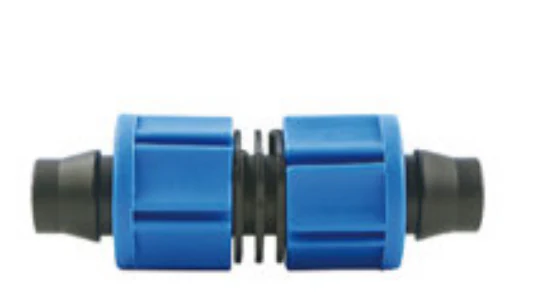
Coupling with catalogue-backed technical fields clearly documented. Compare the exact record, variant and project requirements before a technical enquiry.
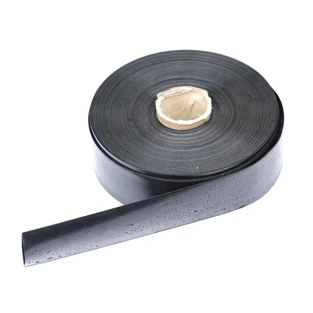
IRRINEX layflat irrigation hose. diameter: 25-125mm; Thickness: 0.5mm-1.2mm; Working pressure: 1-4Bar. Layflat hose conveys water within an irrigation arrangement. Select the material, dimensions and connection configuration from the exact listing data.
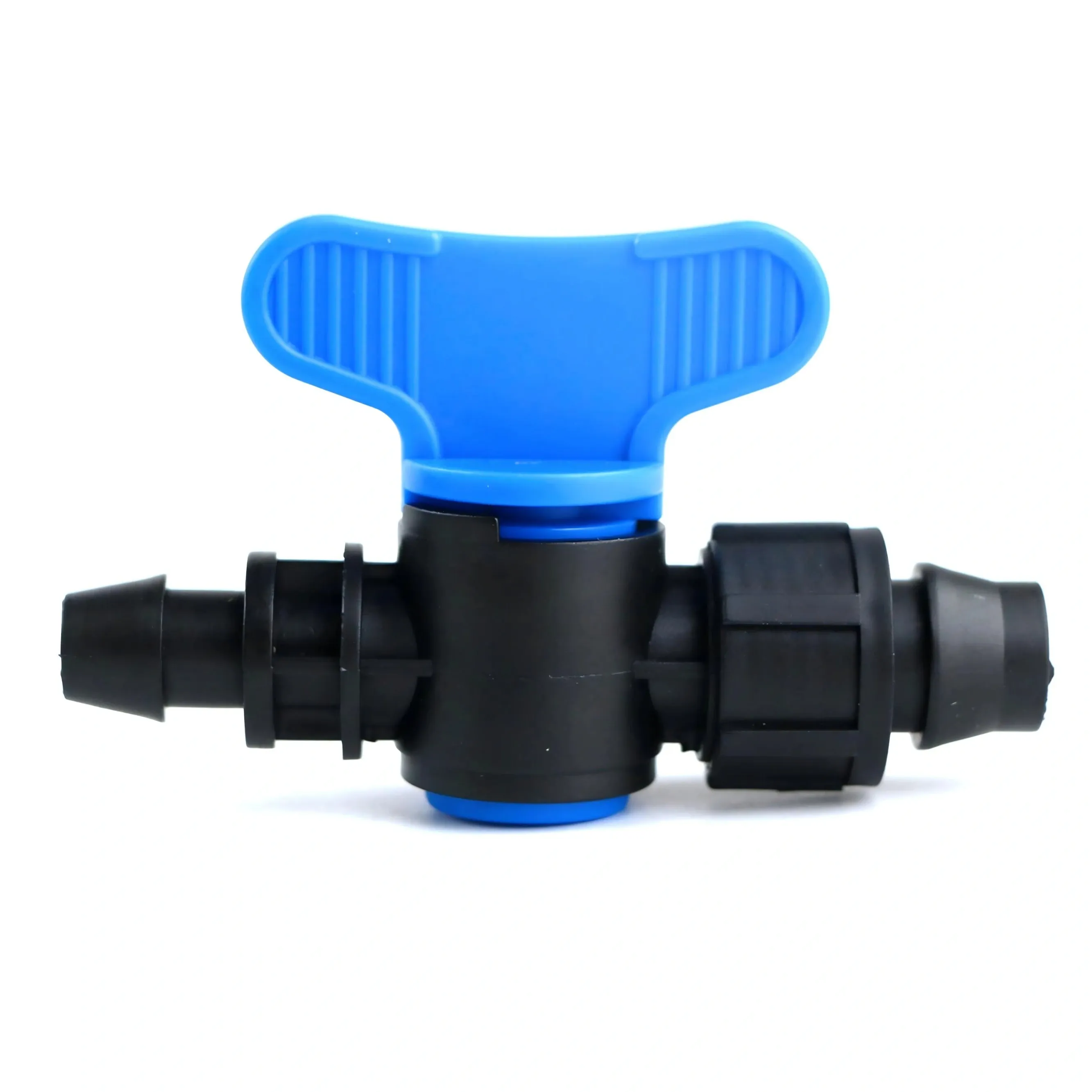
IRRINEX irrigation valve. Diameter: 16mm; Connection size: 16 mm; Working pressure: 0-0.4Mpa; Connection size: 16mm. An irrigation valve forms part of the system's flow-control arrangement. The named valve form and its actual connections should be checked before choosing a configuration.
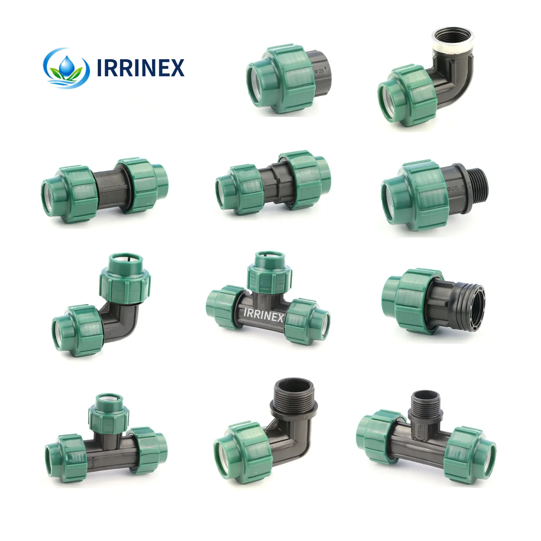
IRRINEX compression pipe fitting. Working Pressure: 10-16bar. A compression fitting joins a matched pipe to the selected connection. Check each pipe and thread dimension for the exact fitting configuration.