Two-Wire Decoder Irrigation: Plan Cable Routes, Splices, and Fault Isolation
A two-wire decoder irrigation plan needs two linked records: where the cable actually goes and which decoder output controls each physical valve. Keep controller station names, device addresses, output channels and irrigated blocks distinct. A shared cable path makes those relationships especially important when a fault interrupts several valves at once.
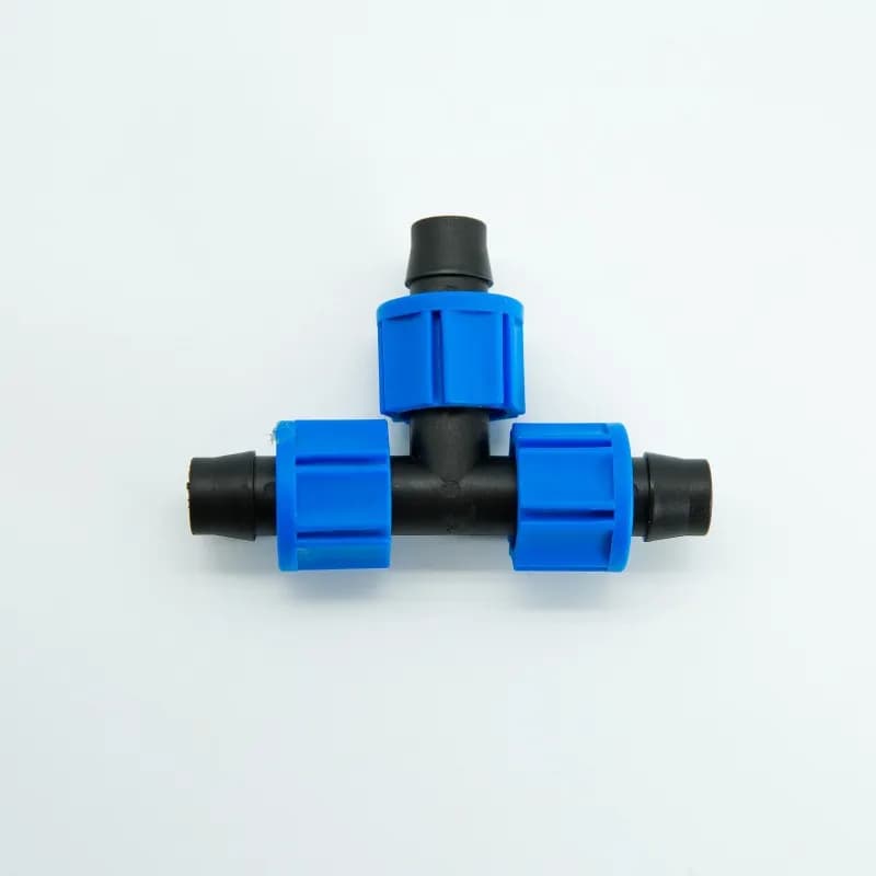
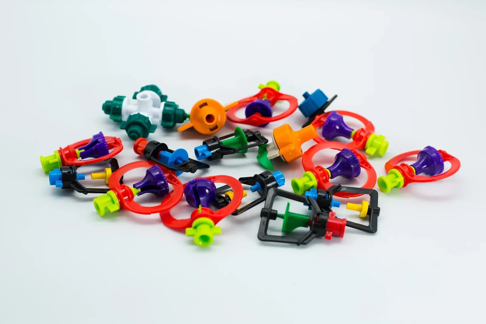
Micro-sprinkler components with coloured frames and connection points, laid out for identification. The photograph illustrates irrigation hardware; it does not show decoders or a two-wire cable network. Photo: IrriNex.
This article develops a route-and-address register and a sectional investigation log for agricultural irrigation. The network, identifiers, lengths and observations below are invented examples. They are not an approved electrical design, product ratings or an IrriNex installation. Qualified personnel must use the exact controller, decoder and protection documentation before installing or changing a field circuit.
1. Define the system family before drawing connections
Record the controller model, output-module version, firmware, approved field devices and compatible solenoids. Identify whether a decoder has one or several outputs, and how the selected system assigns addresses to those outputs. A device serial number, a programmed station address and the operator's block name can be different identifiers. The register should preserve all of them.
Use the irrigation controller architecture comparison if the control family is still undecided. Once a decoder family is selected, obtain its own limits for cable construction, branch arrangements, path loading, simultaneous operation, decoder-to-solenoid leads and surge protection. Two conductors do not establish protocol compatibility or a universal operating voltage.
Do not turn one manufacturer's example into a farm-wide rule. Permitted branches, polarity, cable loops, spare tails and grounding arrangements vary with the complete system. A service loop of extra cable stored for access is also different from an electrically closed ring. The drawing must make that distinction explicit; never close a path back to another output or branch merely because it looks like useful redundancy.
Confirm how the controller reports a missing device, shorted path or unresponsive output. Some systems provide device replies; others expose more limited diagnostics. Write down what each available indication actually means before using it as evidence. An absent acknowledgment has a different meaning when the selected system does not provide acknowledgments at all.
2. Join the address register to the hydraulic block map
Give the controller, accessible junctions, decoder housings and valves durable field labels. Add a physical location that another technician can find without remembering the installer’s route. Use a readable plan, photographs and surveyed references where needed. Mark an unverified cable route as unverified rather than joining nearby boxes with an assumed line.
In the fictional register below, controller C serves three decoder housings and four independent output assignments. D-N has two outputs; D-S and D-E each have one. Assume the chosen equipment permits this arrangement and the shown addresses. The numbers deliberately do not follow the cable's geographical order.
| Decoder housing / location | Output | Assigned address | Valve / block | Cable arm |
|---|---|---|---|---|
| D-N / JN | A | 21 | V-NW / northwest orchard | North |
| D-N / JN | B | 22 | V-NE / northeast orchard | North |
| D-S / JS | A | 73 | V-S / southern block | South |
| D-E / JE | A | 24 | V-E / eastern block | South, beyond JS |
Add the installed serial identifiers, actual programming readback where supported, valve and coil references, and verification date to the working register. Check uniqueness within the addressing scope required by the system. Do not deliberately duplicate an address to make two blocks operate together; use the approved scheduling and output arrangement.
Address 24 is electrically downstream along the south arm in this example, despite being numerically close to the northern addresses. Sorting a spreadsheet by address therefore cannot establish cable order or a fault boundary. Also count output assignments separately from physical decoder housings when checking device capacity or preparing spare parts.
3. Record routes as connected segments, not a cable total
Draw controller C to junction J0, then the north arm to JN and the south arm through JS to JE. Label each segment at both ends. Record actual routed length, cable specification, sleeves, access constraints and every intermediate joint. Any hidden joint or undocumented diversion remains an open survey item.
Oklahoma State University's irrigation construction specification links valve grouping, wire routes and record drawings, and specifies a particular two-wire installation. It is a campus project specification, not a universal farm wiring standard. Its equipment, burial depths, cable sizes, grounding intervals and prohibition on loops must not be copied as generic requirements.
The following hypothetical cable lengths already include route diversions and planned service slack. Each value is the length of a cable containing the pair, not the sum of its two individual conductors. Assume the illustrated open-ended topology has been approved for this fictional system; the table only checks route arithmetic.
| Segment | Route | Segment cable length | Distance from C to the endpoint |
|---|---|---|---|
| T | C to J0 | 120 m | 120 m |
| N | J0 to JN | 230 m | 350 m |
| S | J0 to JS | 310 m | 430 m |
| E | JS to JE | 140 m | 570 m |
Total mapped cable is 120 + 230 + 310 + 140 = 800 m, while the longest shown controller-to-decoder route is 120 + 310 + 140 = 570 m. Neither number establishes electrical acceptability. The selected design method may also depend on connected devices, active loads, shared segments and waveform behavior. Do not apply a simple conventional station-wire voltage-drop calculation as a decoder-path approval.
4. Make splice locations inspectable and identifiable
Give each joint a location identifier and a connection record showing which cable ends and device leads meet there. Distinguish a cable-only branch joint from a decoder connection and from an output-to-solenoid connection. Photograph labels and the connection arrangement before concealment, following the project's inspection process.
Select the approved connector for the actual conductor sizes, conductor count and wet or buried environment. Record its exact specification and installation instruction. A waterproof-looking cap is not evidence of a valid connection; additional gel or tape does not automatically make an unapproved splice acceptable. Preserve cable slack and strain relief as required by the equipment instructions without inventing a standard length for every box.
Place planned sectional access where the approved design allows it and where service personnel can reach it. A manufacturer's approved isolating accessory can have electrical and environmental requirements that a generic switch does not meet. The map should show which conductors and downstream devices the chosen access point separates, without instructing an operator to improvise cuts in a live path.
Keep surge and grounding components visible in the records, including their locations and required inspection results. Do not use a grounding electrode as a substitute for a path conductor, combine unrelated controller outputs, or remove protection to clear a fault message. If expansion changes the protected layout, have that design reviewed before energizing the added section.
5. Prepare a safe sectional investigation
First preserve the original symptom: controller time, alarm text, affected addresses, active program, recent repairs and weather or excavation events. Save the configuration before reprogramming devices. Reassigning addresses at the outset can destroy the distinction between a wiring fault and a mapping error.
Oregon State University's April 2026 irrigation inspection guide calls for power disconnection before electrical servicing and qualified assistance where safety is uncertain. For decoder work, the responsible technician must identify all energy sources and prevent automatic or remote restart using the equipment's isolation procedure. Disabling a watering schedule alone is insufficient.
Do not cut, splice or move conductors while energized. Any approved diagnostic operating check is a separate controlled stage after the connections and protective covers are restored. Confirm beforehand whether the manufacturer permits the intended partial network to operate and which pump, master-valve or sensor functions would be unavailable. Maintain the approved pump and valve interlocks throughout the investigation.
Do not apply a megohmmeter or other high-voltage insulation test to cable with decoder electronics, controller interfaces or surge devices still connected. If an isolated cable test is required, a qualified specialist must define and verify the disconnected boundary, appropriate instrument and permitted test procedure. The conventional station-and-common wiring worksheet covers a different circuit and is not a decoder-bus test recipe.
6. Interpret a branch result without condemning a decoder
Consider invented observations from the mapped network. Assume its documented diagnostics can identify the expected responses shown below, and the manufacturer allows the isolated north-only test configuration. The technician changes connections only under verified isolation, then restores protection before each permitted operating observation. This is a record example, not an instruction to reproduce a fault.
| Record | Connected configuration | Observation | Supported next decision |
|---|---|---|---|
| R-A | Original complete network | Path alarm; northern addresses 21 and 22 respond, while 73 and 24 do not | Prioritize the shared south arm while retaining other possible causes |
| R-B | Approved north-only configuration; south arm separated at J0 | Path alarm clears; 21 and 22 respond; 73 and 24 are not tested | Investigate the removed branch, its loads and the changed loading condition |
| R-C | Original topology restored after a documented repair | All four mapped outputs respond and their individual valve/block checks pass | Review the repair evidence and restoration record before release |
R-B associates the symptom with a changed network configuration. It does not prove that D-S, D-E or a particular buried joint is defective. Reduced loading can also change a marginal supply or connection's behavior. Further permitted sectional checks need their own boundaries and observations; avoid replacing several decoders simply because their addresses stopped responding.
Separating the south arm removes two of the four mapped outputs from this test configuration, even though only three decoder housings exist overall. Those unavailable outputs are not successful tests and must not disappear from the service log. Do not assume their valves closed when communication or power was removed; establish the actual hydraulic state using the approved isolation and operating arrangements.
7. Restore identities as carefully as connections
For a replacement decoder, retain the removed device's identifier, the replacement identifier, assigned outputs and configuration revision. Verify programming using the supported method and check for unintended duplicate assignments. Update both the route drawing and the address register if a box, cable arm or output changes.
During supervised, authorized operation, confirm each physical valve and the intended irrigated block separately. Observe the required start and stop behavior and record relevant hydraulic evidence. Mainline flow alone cannot establish correct addressing: another block, bypass or manually open valve may explain the water movement. A communications response similarly does not prove valve movement.
Account for every temporary disconnection and test device, restore required protection, and reconcile pending programs before returning to automatic operation. The local operation and recovery guide covers stale information and pending commands; this route log should identify which physical network was restored when that recovery was checked.
Hand over the final topology, output register, joint records, approved component references and linked investigation files together. Preserve earlier revisions and mark any unresolved location or untested function explicitly. The useful result is a traceable path from an operator's block name to the exact output and accessible cable section, so the next fault starts with evidence instead of an address-number guess.
8. Frequently asked questions
Does the next address mean the next decoder along the cable?
No. Address allocation depends on the selected system and programming. Record physical cable order separately, including multiple outputs in one decoder housing. Verify the valve and block associated with each assignment.
Can a spare cable end be connected back to form a ring?
Only if that exact arrangement is explicitly approved for the installed system and incorporated into its design. Do not improvise a closed loop or connect different outputs together. A stored length of service slack does not authorize an electrical ring.
Does a cleared alarm prove the disconnected branch contains a failed decoder?
No. It shows that the symptom changed with the connected configuration. Cable, splices, protection, devices and load-dependent behavior remain possible contributors. Preserve the test boundary and obtain further approved evidence before identifying a failed part.