
Irrigation Zone Valves with Low Differential Pressure: Check Opening Reliability
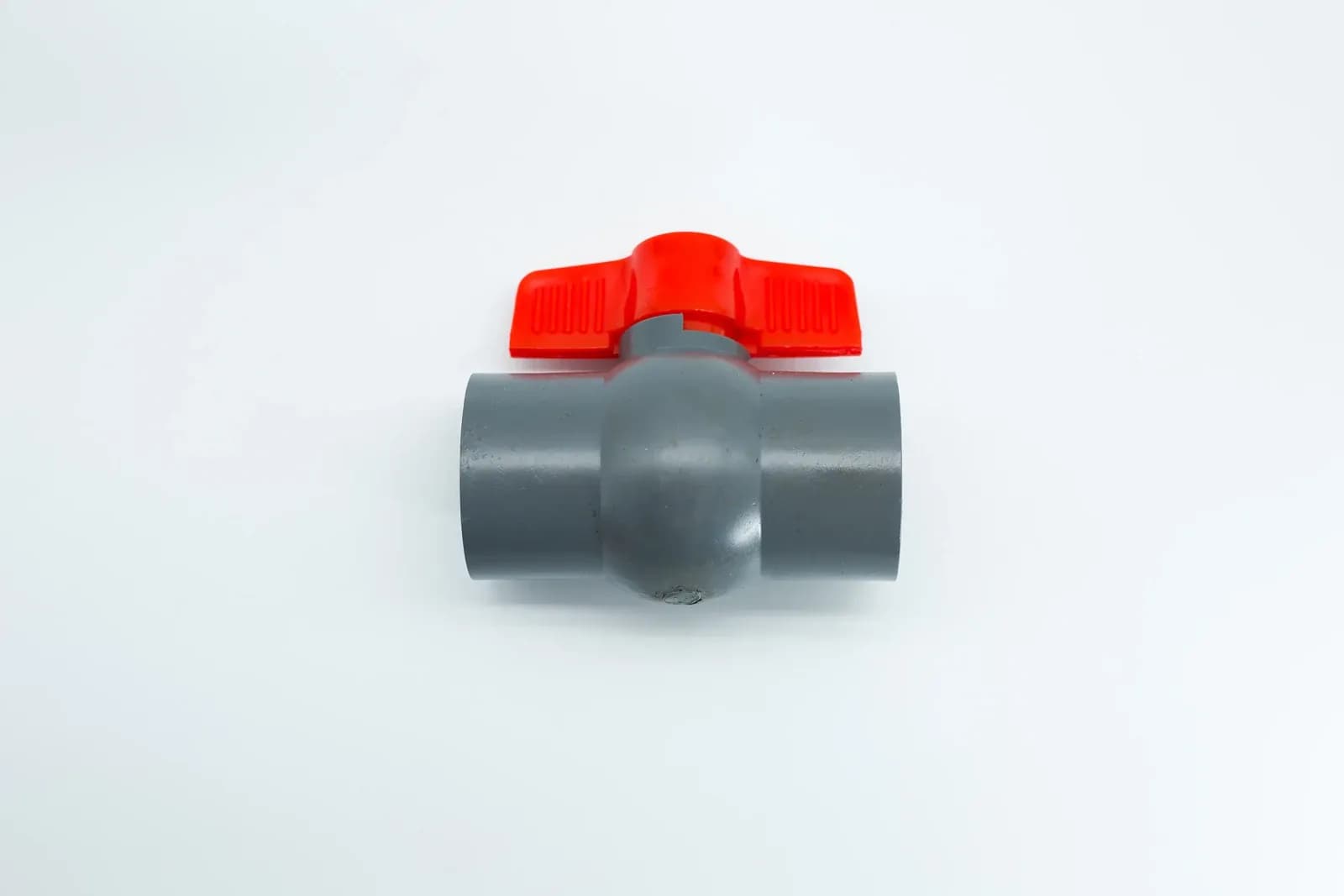
An irrigation zone valve can have adequate inlet pressure and still lack the pressure difference needed to open or remain open. Check the exact valve assembly's operating requirements against simultaneous inlet and outlet measurements during the intended start and irrigation duty. For a gravity-fed system, also check the lowest permitted tank level. A pressure rating, an energized solenoid and an open command do not establish hydraulic opening reliability.
Manual irrigation valve with a grey body and red wing handle. The photograph does not establish this valve’s minimum operating differential or verify its opening performance. Photo: IrriNex.
This guide builds a low-differential-pressure assessment for agricultural irrigation zone valves. It separates the equipment's actuation requirement from the pressure needed to deliver water, then uses original numerical examples to show when a measurement is too uncertain to support acceptance. Every equipment limit and field reading in those examples is hypothetical.
1. Identify which pressure requirement the specification actually states
Ask for the complete model, size, actuator, pilot configuration and water-service conditions. Locate the operating instructions for that assembly. The words minimum pressure are incomplete unless the document identifies the measurement points and the function being supported. A minimum inlet pressure measured against atmosphere is different from a minimum inlet-to-outlet differential.
| Specification entry | What it describes | What it does not establish |
|---|---|---|
| Minimum inlet pressure | Required pressure at a defined supply point and reference | The difference between inlet and outlet |
| Minimum operating differential | Required pressure difference between stated ports for a stated function | Available downstream irrigation pressure |
| Maximum working pressure | The assembly's permitted pressure under defined service conditions | Successful opening at low differential pressure |
| Minimum regulating flow | The flow boundary for specified regulating performance | A universal minimum flow for every on-off valve |
Some requirements apply when opening; others apply while holding a position, changing state or regulating. Record those distinctions instead of merging them into one number. If a document does not specify a behavior, request clarification for the intended duty. Do not borrow a minimum from another valve that shares the same connection diameter.
The irrigation valve selection guide helps identify the required service. Use the separate pressure-reducing valve operating-envelope guide when pressure regulation is part of the assembly. This opening assessment does not replace that regulation review.
2. Separate hydraulic actuation from water delivery
The University of Florida explanation of irrigation control valves describes diaphragm operation through internal pressure differences and distinguishes direct solenoid movement from pilot action. Consequently, electrical power can initiate a hydraulic process without supplying the force that moves the main closure element. The external port differential and the internal chamber pressures are related through the particular circuit; they are not interchangeable measurements.
For an assembly that relies on a specified line-pressure differential, the available differential must satisfy its documented requirement. A configuration using a separate hydraulic control supply needs that supply checked at the relevant operating states. Identifying a double chamber alone does not establish a universal low-pressure capability: the plumbing arrangement and operating data still matter.
A mechanically driven or appropriately specified direct-acting valve may be able to move its closure element without a positive inlet-to-outlet differential. That capability does not create water-delivery pressure. An open water route still needs adequate total head to supply the intended flow through the valve, pipework and emitters. Zero minimum operating differential must never be interpreted as full rated flow at zero available head.
Read the diaphragm, pilot and solenoid explanation for the basic sequence. In the assessment record, keep three questions separate: did the correct command arrive, did the valve perform the specified movement, and did the intended branch receive water under its required conditions?
3. Measure the two ports during the same operating event
Identify inlet tap U and outlet tap D on the actual drawing. Measure at the points required by the supplier's specification. A gauge before a long connecting pipe and another after several fittings measure a larger assembly than the valve alone. Record those intervening components if the taps cannot be placed at the defined boundaries.
For two pressure readings using the same reference, the port differential is ΔP = PU − PD. Gauge and absolute pressure cannot be mixed in that subtraction. Differences in instrument elevation or liquid-filled sensing lines also need appropriate treatment before the values represent the intended ports. A pressure differential between unequal pipe sections is not automatically the irreversible valve loss because velocity and elevation terms can contribute to the energy balance.
Take synchronized measurements. Subtracting an inlet reading before a pump ramp from an outlet reading after it does not produce the differential at either time. Identify the logger's sampling interval, sensor response, calibration status and time reference. Instruments suitable for a steady operating check may still miss a short transition; do not claim to have verified an event that the recording system cannot resolve.
Include actual branch flow and the operating combination. A large inlet-to-outlet difference can occur across a closed or restricted valve, so a favorable differential alone is not proof of opening. Conversely, a very small differential across an open low-loss route may be normal for equipment explicitly suitable for that condition. Interpret the measurements with the assembly's requirements and observed water delivery.
4. Check whether measurement error can change the decision
Assume the relevant valve requirement is a minimum differential of 15 kPa during the condition under review. Two simultaneous gauges indicate 120 kPa at U and 100 kPa at D. Assume each complete pressure measurement has an applicable bounded error of ±4 kPa, including the effects relevant to this example. The indicated differential is 20 kPa, but its possible range is wider.
The smallest difference is (120 − 4) − (100 + 4) = 12 kPa. The largest is (120 + 4) − (100 − 4) = 28 kPa. Because 15 kPa lies within that interval, these readings do not establish that the minimum requirement was met. They also do not prove that it was violated. The correct result is unresolved by this measurement.
| Measurement arrangement | Assumed applicable error bounds | Possible differential | Comparison with 15 kPa |
|---|---|---|---|
| Two separate pressure measurements | ±4 kPa for each reading | 12 to 28 kPa | Cannot establish the minimum |
| Direct differential measurement | ±1 kPa for the differential | 19 to 21 kPa | Clears the numerical minimum for this observation |
| Two pressure measurements after a verified improvement | ±1 kPa for each reading | 18 to 22 kPa | Clears the numerical minimum for this observation |
This is worst-case interval arithmetic using stated bounds, not a statistical confidence interval. It assumes no known cancellation between the separate measurement errors. An instrument's advertised accuracy must first be interpreted correctly: a percentage of full scale, a percentage of reading and a fixed pressure increment are different specifications. More displayed decimal places do not reduce the underlying error.
A passing numerical comparison is still only one part of acceptance. The instrument must tolerate the actual static pressure, environment and possible overload, and the test must cover the required operating states. Any additional project margin belongs in a stated decision rule. Do not quietly treat the 4 kPa clearance in the direct-measurement row as a universal design reserve.
5. Test a gravity-fed duty at the lowest allowed water level
For an open tank, measure vertical height from the water surface to the reference elevation, rather than from the tank outlet or its support frame. Rice University's OpenStax treatment of fluid pressure derives the static contribution ΔP = ρgh. Tank width changes storage volume; it does not increase this pressure at a fixed water-surface height.
Consider a hypothetical constant-density water system with ρ = 1,000 kg/m³ and g = 9.81 m/s². For the proposed delivery duty, assume the route from the open tank surface to the valve inlet consumes 6 kPa of the pressure-equivalent head, including its applicable loss and velocity terms. Assume 15 kPa is required at the valve outlet and the proposed valve requires a 15 kPa port differential for this operating condition.
| Surface height above valve reference | Static pressure contribution | Proposed inlet pressure after 6 kPa allowance | Difference remaining above required 15 kPa outlet |
|---|---|---|---|
| 3.0 m | 29.43 kPa | 23.43 kPa | 8.43 kPa |
| 2.0 m | 19.62 kPa | 13.62 kPa | −1.38 kPa |
| 4.0 m | 39.24 kPa | 33.24 kPa | 18.24 kPa |
At 3.0 m, the assumed 15 kPa valve requirement exceeds the available 8.43 kPa. At 2.0 m, the negative remainder means the proposed duty cannot even supply the required outlet pressure under these assumptions. It does not predict reverse flow or the actual operating pressure: once the duty changes, flow-dependent losses and equipment behavior must be solved again.
The 4.0 m row clears this simplified numerical screening, but it is not permission to raise a tank. Structural support, source operation, complete hydraulic behavior and equipment limits remain separate design matters. Under the same fixed-duty assumptions, the minimum height for the two pressure requirements plus the upstream allowance is (15 + 15 + 6)/9.81 = 3.67 m, rounded, before any additional project reserve. Use the drip irrigation pressure-budget method to replace the assumed allowance with the actual route assessment.
6. Cover startup, small zones and retained downstream pressure
Review the approved startup sequence from its actual initial state. A downstream pipe that has drained presents a different initial condition from a branch retaining pressure. A pump may ramp while the valve command is active. An external pilot supply may become available at another time. Record these conditions rather than assuming that the previous steady irrigation reading applies throughout opening.
For the smallest permitted zone, compare the measured operating condition with the exact valve specification. Lower flow can reduce the pressure difference across an open route, but that observation does not establish a failure for every valve. The decision depends on whether the assembly requires a minimum differential for the function being assessed. Check the largest duty too, because its upstream losses can reduce the available supply.
Repeat the relevant checks after an approved interruption or changeover where retained outlet pressure can differ. Keep pump protections and the authorized water path in service. Do not create a discharge, defeat an interlock or loosen pilot tubing to manufacture a favorable pressure difference. Use the electrical-versus-hydraulic troubleshooting guide if the correct command or pilot operation remains uncertain.
7. Resolve the failed condition before accepting the valve duty
When measurement is inconclusive, improve the measurement first. When the required differential is unavailable, identify whether the cause is the source condition, upstream loss, retained downstream pressure, operating sequence or unsuitable actuation arrangement. A larger nominal valve is not an automatic remedy: it can change the hydraulic loss without resolving the required actuation mechanism.
Provide the equipment supplier or irrigation designer with the marked pressure taps, synchronized traces, measured flow, lowest source level and exact assembly identification. Compare documented alternatives suitable for those conditions. A different actuator or pilot supply can introduce additional power, control and failure-state requirements, so its complete configuration needs review.
The acceptance record should identify the assessed conditions, governing requirement, instrument bounds, observed movement and water delivery, result and unresolved actions. Retest affected duties after a change. Preserve the original failed or inconclusive result beside the new evidence so operators can see what changed and which conditions are now supported.
8. Questions about irrigation valves at low differential pressure
Does a high inlet gauge reading prove that the valve has enough differential pressure?
No. The outlet pressure and the specified measurement points are also needed. A high pressure on both sides can leave little port differential. Use simultaneous readings with compatible references and enough accuracy to resolve the requirement.
Will a zero-differential valve solve every gravity-fed irrigation problem?
No. It may address an actuation requirement when explicitly suitable for that service, but it does not supply the head needed for the intended flow, pipe losses and emitter pressure. Assess delivery at the minimum permitted water level as well as valve movement.
Can one successful opening establish reliability for all zone combinations?
No. It demonstrates behavior under the recorded test conditions. Acceptance needs the project's defined operating cases, suitable measurements and repeat checks where required. A changed pump, tank level, zone layout or pilot arrangement can require a new assessment.


