Irrigation Valves That Will Not Close: Find Pilot Leaks, Debris, and Backpressure
An irrigation valve that will not close needs a record of where water is coming from, what closing command was delivered, and whether its hydraulic control circuit reached the intended state. Water leaving a low sprinkler after shutdown does not by itself prove leakage through the main seat. Conversely, an “off” icon does not prove that a pilot passage closed. Separate continuing inlet flow, pilot discharge, downstream drainage and another downstream supply before replacing parts.
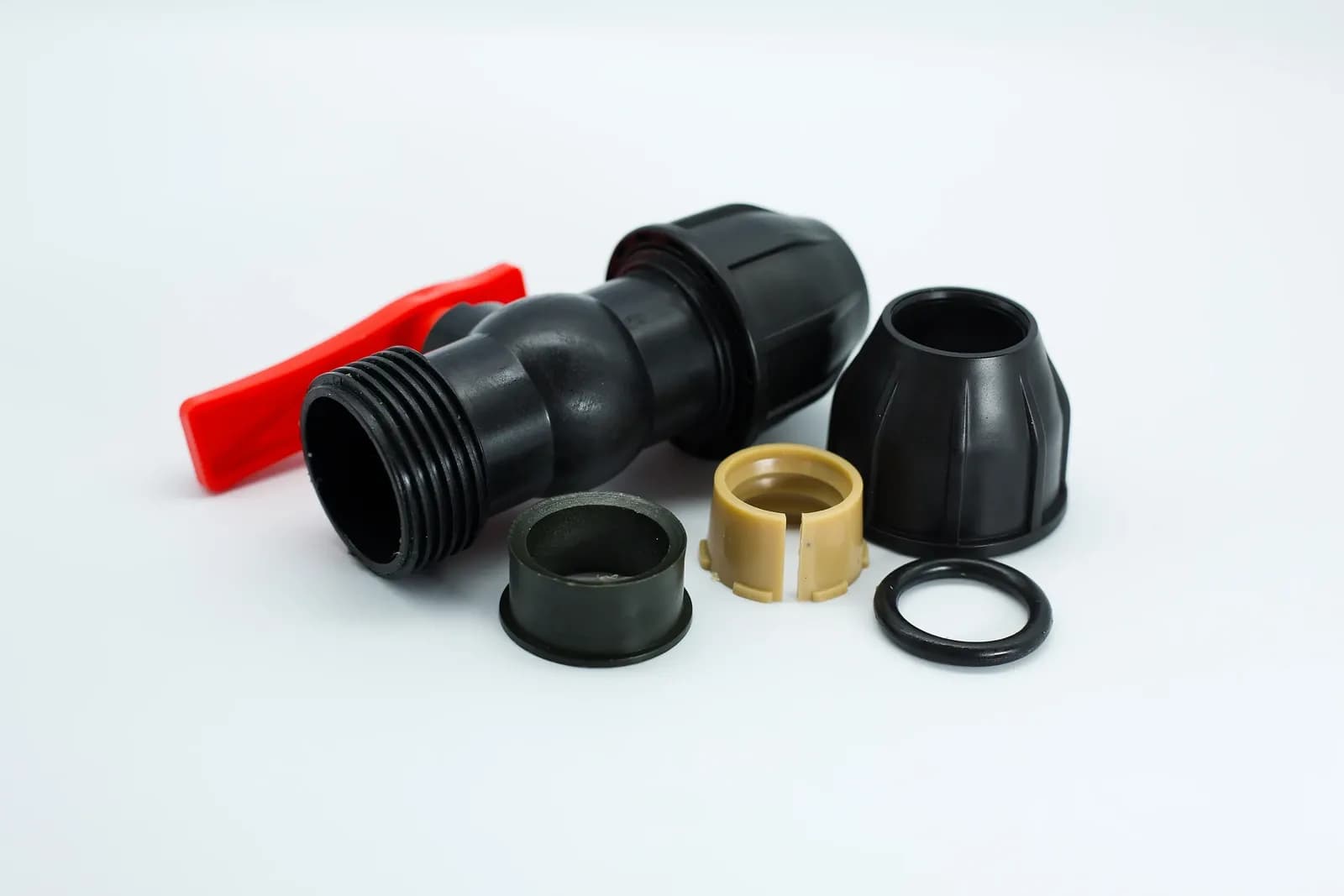
Manual irrigation valve and detached connection components, including an O-ring. This product photograph illustrates component identification; it does not show a pilot-operated valve or a diagnosed closing fault. Photo: IrriNex.
Establish a safe closing-fault record
Identify the valve, its flow arrow, actuator type, pilot arrangement and the pipework it actually controls. Record the supply condition, open zones, downstream connections and fault time. A valve that never closes after installation suggests different questions from one that started passing water after maintenance. Photograph labels and existing connections while the installation remains in its normal protected state.
If uncontrolled irrigation threatens equipment or the crop, use the site's approved isolation and pump sequence. Closing a common supply abruptly can create a separate transient problem. Internal inspection requires isolation, prevention of unintended restart and verification that trapped pressure has been relieved. Do not loosen a bonnet, solenoid, pilot tube or gauge fitting to discover whether it is pressurized. Testing at installed ports and electrical measurements belong to competent personnel using the specified procedure.
Use the closing complaint to define an observable result: continued inlet volume, continued outlet discharge, a failed command acknowledgement, or an abnormal chamber-pressure trace. These are different observations. The basic mechanism is explained in how irrigation diaphragms, pilots and solenoids work; the record below concentrates on proving a closing failure and narrowing its location.
Separate tail drainage from water still entering the assembly
A lateral contains water after the supply valve shuts. Elevation differences can let that stored water drain through lower outlets while air enters elsewhere. Observe whether discharge declines, where it appears and whether water is still crossing a suitably located inlet meter. There is no universal waiting period: lateral volume, slope, outlet devices and air entry all affect the drainage history.
Map the meter boundary before interpreting it. An upstream branch meter can include water feeding the pilot circuit, an external pilot drain, a bypass or another outlet. Continued registered volume therefore proves incoming water within that mapped boundary, subject to meter capability; it does not automatically locate a leak at the main diaphragm seat. A meter unable to resolve the suspected low flow cannot establish a tight seal from a stationary display.
| Observation | Record alongside it | What remains unresolved |
|---|---|---|
| Water at a low outlet after shutdown | Time history, elevation and inlet-meter behavior | Stored drainage versus replenished water |
| Continued inlet volume | Every branch and pilot discharge inside the meter boundary | Main-seat leakage versus another flow path |
| Controller shows off | Actual actuator type and verified closing signal | Electrical indication versus hydraulic response |
| Downstream remains pressurized | Other feeds, trapped volume and downstream demand | Trapped pressure versus an active external supply |
For a deliberately simple measurement example, assume a suitable calibrated instrument has reliably measured 4 L entering the mapped assembly in 5 minutes, after the agreed observation window. The average incoming rate is 4 ÷ 5 = 0.8 L/min, equivalent to 48 L/h if that rate persists. These are hypothetical measurements, not a leakage allowance. Record the actual instrument range, resolution and uncertainty; the arithmetic cannot make an unsuitable meter sensitive enough.
A falling downstream pressure can accompany either ordinary drainage or a continuing small leak into an open lateral. A steady downstream pressure can be trapped water with no continuing flow. Pressure and volume evidence answer different questions, so retain both traces instead of treating either as a universal closure indicator.
Verify the command for this actuator
Confirm what “close” means for the installed configuration. A conventional normally closed solenoid, a normally open hydraulic arrangement and a pulse-operated latching actuator do not share one electrical test. Removing continuous power may close one configuration; a latching unit may need a specified closing pulse. A controller status message documents its reported state, not necessarily the signal received at the valve or the resulting plunger position.
Have the responsible technician verify the permitted closing signal, connections and any manual override against the exact documentation. Do not improvise energization, apply an assumed voltage, interchange actuator types or adopt a generic number of turns for a manual bleed. A manual pilot override left in an opening position can sustain an unintended drain path even when the controller has finished its program.
Keep detailed electrical diagnosis in the electrical-versus-hydraulic solenoid troubleshooting guide. Here, record whether the correct closing command was actually verified and whether the hydraulic response followed. If the command remains unverified, do not label the diaphragm defective merely because water continues to pass.
Trace the chamber feed and pilot discharge separately
Consider one explicitly assumed reference arrangement: inlet water feeds the upper control chamber through a restriction, and a pilot passage can discharge chamber water to the downstream side. For this arrangement, closing the pilot discharge allows chamber pressure to recover toward inlet pressure and helps the main valve close. Effective areas, springs, friction, differential pressure and the actual internal geometry determine the resulting force and travel.
This description is conditional. Other arrangements use separate supply and exhaust connections, different pilot routing or a different normal state. The University of Florida explanation of irrigation control valves describes differential-pressure actuation; it is not a universal pressure-ratio specification for every diaphragm valve.
In the assumed arrangement, debris blocking the chamber feed can prevent pressure recovery. Debris preventing a pilot seat or plunger from sealing can maintain discharge. A damaged diaphragm can create another communication path. An obstructed exhaust passage, however, may impede opening rather than explain failure to close. “The pilot is blocked” is therefore an incomplete diagnosis until the blocked passage and its intended function are identified.
The USDA NRCS microirrigation chapter, printed page 7-50 distinguishes pilot configurations and discusses clean water for small control passages. Use the actual schematic to mark inlet feed, restriction, chamber, pilot seat and discharge destination. Do not reroute a tube or change a restrictor to test a theory while the assembly is pressurized.
Compare pressures with a documented reference, not a universal ratio
The following original example assumes the reference arrangement above, approved measurement ports, comparable operating conditions and readings taken after a documented observation window. All pressures are gauge pressures in bar, referred to the same elevation or corrected for elevation. The downstream boundary is deliberately controlled for the comparison; an open field lateral need not maintain these pressures. Instrument uncertainty and changing source pressure must be considered before interpreting small differences.
| Observation | Inlet Pu | Chamber Pc | Downstream Pd | Pu − Pc | Pu − Pd |
|---|---|---|---|---|---|
| Previously accepted closed reference | 3.0 | 2.9 | 1.0 | 0.1 | 2.0 |
| Suspect A: incoming flow continues | 3.0 | 1.1 | 1.0 | 1.9 | 2.0 |
| Suspect B: incoming flow continues | 3.0 | 2.9 | 1.0 | 0.1 | 2.0 |
| Changed boundary: downstream source present | 1.8 | 1.7 | 2.2 | 0.1 | −0.4 |
The accepted reference must have its own documented closure evidence and measurement limitations. It is not established merely by choosing the first row's pressures. In suspect A, the chamber fails to reproduce the reference pressure while inlet and downstream readings remain comparable. That supports investigating the feed restriction, continuing pilot discharge or another chamber leak. It does not uniquely identify a failed component.
Suspect B reproduces the reference chamber reading but still has measured incoming flow. Investigate whether the main sealing surfaces can seat, whether movement is obstructed, and whether the meter includes a pilot drain or bypass. Chamber pressure alone neither proves a sound diaphragm nor establishes that every hydraulic closing force is sufficient. Do not convert the table's pressure differences into a universal pass/fail threshold.
The changed boundary has Pu − Pd = −0.4 bar. This establishes an adverse pressure gradient at those taps, not the actual direction or quantity of flow. Valve internals, connected routes and any reverse-flow provisions still matter. The chamber number cannot be interpreted using the first row's boundary assumptions. Identify the downstream source and apply the installation's approved operating procedure.
Distinguish sealing defects from system backpressure
After safe isolation and verified depressurization, authorized inspection may reveal debris on a seat, a torn diaphragm, damaged sealing surfaces, worn seals or incorrect reassembly. Record the actual finding, its location and the prescribed corrective action. Retain evidence of debris type and upstream filtration condition; replacing a seal without addressing recurring contamination can leave the cause unresolved.
The University of Florida irrigation maintenance guidance includes valve diaphragm, seat and seal checks, as well as checking gauges and meters. Use the component manufacturer's service method for the installed materials and assembly. Generic scraping, solvents or tightening instructions can damage parts and do not belong in a universal closing-fault checklist.
Backpressure is a system condition, not automatically a defective valve. It may come from another pump, an elevated connected line or an interconnected zone. Separate a trapped downstream pressure from a supply that can continuously replenish water. A zone-control valve is not automatically an approved backflow-prevention assembly; the check-valve and backflow-preventer guide explains why those functions require separate evaluation.
A regulating valve also has a different duty from a valve required to isolate a zone. Its pilot adjustment and regulating envelope do not by themselves establish shutoff performance. Check the specified closing configuration and permitted leakage separately from the minimum-flow and stable-regulation assessment. Do not use an arbitrary pressure adjustment to conceal a closing fault.
Complete the record with a controlled verification
After the approved repair and reassembly, verify closing under documented conditions within the equipment's permitted operating envelope. Record the command, relevant pressure history, incoming volume and downstream behavior together. Include the allowed observation window, the basis for leakage acceptance and the measurement capability. A single photograph of a stationary gauge does not replace this record.
| Record field | Required evidence | Decision it supports |
|---|---|---|
| Configuration and boundary | Valve identification, schematic, source, other feeds and meter coverage | Whether the observations describe this assembly |
| Command and response | Verified close signal and time-aligned hydraulic observations | Whether control and hydraulic action agree |
| Finding and correction | Actual defect or unresolved cause; authorized service performed | Whether the cause was demonstrated |
| Retest and acceptance | Operating conditions, observation window, leakage criterion and instrument limits | Whether closure was verified for the tested duty |
Where multiple normal supply or downstream conditions occur, use an approved representative verification plan rather than deliberately creating an abnormal pressure event. Retain unresolved cases explicitly. If the equipment cannot meet its specified closing duty, restrict operation through the site's normal process until the cause or selection is corrected; repeated controller commands are not evidence that the fault has disappeared.
Frequently asked questions
Does continued dripping mean the main valve leaks?
It may be stored lateral drainage. Compare the discharge history with a capable inlet measurement and a map of other feeds. Continuing inlet flow still needs localization because the meter may include pilot discharge or a bypass.
Should chamber pressure always equal inlet pressure when closed?
No universal equality or percentage applies. Pilot routing, restrictions, leakage allowances, instrument uncertainty and the valve's construction matter. Compare with the exact documentation and a valid reference under comparable boundary conditions.
Can a controller reset fix a valve that will not close?
A control problem may require a documented control correction, but a reset does not remove seat debris, repair a diaphragm or eliminate a downstream source. Verify the correct closing command and the resulting hydraulic closure before accepting the system.