Irrigation Valve Position Feedback: Confirm That a Command Became Flow
Irrigation valve position feedback should identify what was measured, where it was measured and when the observation was made. A controller acknowledgment confirms a communication event. An end-position contact indicates the state of its sensing mechanism. A correctly located flow meter provides evidence of water movement. Combine those observations before describing a commanded valve as delivering water to the intended branch.
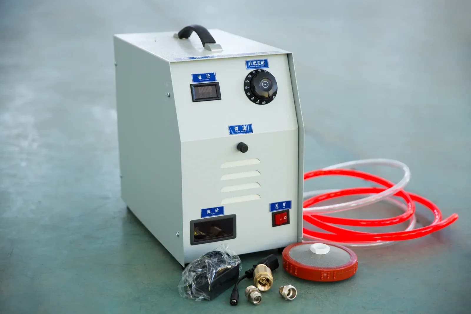
Portable fertigation control box with display windows, adjustment knobs and tubing. This photograph does not establish valve-position feedback or branch-flow confirmation capability. Photo: IrriNex.
The practical deliverable is a feedback record for each valve: signal meaning, physical sensing point, valid states, measurement age and the hydraulic evidence needed for the task. The examples below use hypothetical wiring logic, calibration and observations; they are not specifications for an IrriNex controller or a universal installation recipe.
1. Name the evidence behind each displayed state
Start at the field drawing. Identify the valve, actuator, pilot arrangement, position-sensing mechanism, branch meter and pressure taps. Record which component a switch actually follows. A switch driven by a motor gearbox reports something different from a sensor directly following the valve's moving closure member.
The DOE instrumentation and control handbook, Volume 2, describes electric actuators with position limit switches and torque limiters. Its example illustrates why the mechanism matters: stopping at a position setting and stopping at a torque setting are different events. Neither motor current nor a stopped motor alone establishes downstream flow.
Separate the labels “requested,” “command received,” “open position indicated,” “closed position indicated” and “branch flow observed.” These states can be displayed together. They should not overwrite each other so that one green icon conceals which observations are still missing.
Many pilot-operated irrigation valves have no fitted position transmitter. Do not invent an opening percentage from the solenoid command. Confirm what feedback the supplied configuration can provide, and use hydraulic observations where appropriate. For electrical or hydraulic fault investigation, the solenoid-valve diagnostic guide gives the broader test boundary.
2. Decode end-position contacts without guessing the middle
For an illustrative two-contact arrangement, define O = 1 as “the mapped open-end contact is active” and C = 1 as “the mapped closed-end contact is active.” These are interpreted logical states after the installer has verified wiring and input configuration. They do not prescribe normally open or normally closed terminal wiring.
Assume this particular mechanism is designed so the two end contacts cannot both be active at a valid endpoint. The table then defines what the display can say. A different switch mechanism requires its own state definition; do not copy this table into a controller without that check.
| O | C | Supported interpretation | What remains unproved |
|---|---|---|---|
| 0 | 1 | Closed endpoint indicated by the mapped contact | Leak-tight isolation and the actual water boundary |
| 1 | 0 | Open endpoint indicated by the mapped contact | Available water, unobstructed branch and delivered flow |
| 0 | 0 | Neither endpoint is indicated | Whether the valve is travelling, stopped between ends, disconnected or affected by an input fault |
| 1 | 1 | Contradictory indication for this specified mechanism | A valid physical endpoint; inspect the sensing and input chain |
The 0/0 state does not mean “50% open.” It can be a normal observation during travel, but it also requires a defined response if the permitted travel interval ends without an endpoint. The 1/1 state should not be resolved by giving the open contact priority merely to produce a convenient display.
Document how an input behaves when its wire breaks or power is lost. Depending on the circuit, a disconnected wire can resemble a legitimate contact state. A simple binary input does not automatically supervise its own wiring. Any claimed fault detection needs the corresponding circuit design and a controlled test.
3. Scale an analog position signal, then state its limits
Suppose the supplied transmitter is explicitly configured to represent closed travel at 4 mA and open travel at 20 mA, with a linear relationship between those endpoints. Under that hypothetical calibration, indicated travel percentage = 100 × (I − 4)/16, where I is the measured current in milliamperes.
A 12.0 mA reading gives 50% indicated travel, while 15.2 mA gives 70%. This calculation describes the quantity assigned to the transmitter. It is not automatically diaphragm lift, ball angle or any other internal movement unless the physical installation and calibration establish that relationship.
If the assumed electrical measurement error is bounded by ±0.08 mA, its contribution to the indicated travel error is ±100 × 0.08/16 = ±0.5 percentage points. That is only the electrical contribution under the example's calibration. Mechanical backlash, linkage condition, transmitter accuracy, endpoint setting and repeatability require their own assessment; the calculation is not a total valve-position accuracy claim.
Do not silently clamp a value outside the configured measurement range to 0% or 100%. For example, 3.0 mA lies outside this example's normal 4–20 mA measurement range. Its actual diagnostic meaning depends on the transmitter and input configuration. This article assigns no universal fault-current threshold.
Also keep travel separate from flow. A valve's flow relationship depends on its design, pressure conditions and connected network. A display of 50% travel does not establish 50% of the branch's maximum flow. Use a suitable flow measurement for the delivery question.
4. Verify the relationship between the indicator and the water path
A 2021 NRC presentation on valve position indication describes industrial cases where the indication did not reliably establish the closure member's position, and discusses additional evidence such as flow and pressure observations. It concerns nuclear-facility testing requirements. The useful engineering lesson here is to verify the relationship between indication and function; its regulatory intervals and requirements are not agricultural rules.
During approved commissioning, compare the displayed position with the accessible local indicator and the defined hydraulic response. Record what can actually be observed without opening a pressure-containing component. A shaft mark may corroborate actuator movement while still leaving the condition of an internal connection unobserved.
Choose pressure taps and flow boundaries that answer the intended question. Upstream pressure can remain high when a branch is closed. Downstream pressure can remain trapped after flow stops. A mainline meter can register another zone or a bypass while the named branch receives nothing.
For branch delivery, identify every flow crossing the branch meter's boundary. If the meter also includes a pilot drain, bypass or another outlet, account for those paths. Pressure readings can help interpret the condition, but neither pressure nor flow alone proves which internal part caused an unexpected result.
5. Match observations to the current command and time window
Retain the command identity, request time, acknowledgment time, field acquisition time and reception time. Fresh network traffic may contain an old sensor sample. A reconnecting gateway may also deliver stored observations out of order. Preserve their original acquisition times instead of presenting every received value as a new field measurement.
Consider an original example with command V17-84 requesting opening at elapsed time 0. Assume field and controller clocks have been checked for the needed time accuracy. Assume this project's observation-age limit is 3 seconds for an instantaneous endpoint sample. That limit is invented for this example and is separate from a permitted valve-travel time.
| Elapsed time | Observation | Supported status |
|---|---|---|
| 2 s | The node acknowledges command V17-84 | Command received; valve movement and delivery remain unconfirmed |
| 6 s | Open-end value arrives, but its acquisition time is −60 s | Sample age is 66 s; reject it as current endpoint evidence |
| 10 s | Newly acquired, valid O = 1 and C = 0 | Open endpoint currently indicated for the mapped mechanism |
| 25 s | A fresh endpoint sample again gives O = 1, C = 0; a valid branch total increases by 36 L over the interval 15–25 s | Current endpoint indication and average branch flow over the stated interval are both available |
The last flow interval starts after the first valid open-end observation. Its calculated average is 36 L/10 s = 3.6 L/s = 12.96 m³/h. If this hypothetical branch's separately established average-flow acceptance band is 10–14 m³/h, that interval passes the stated numerical check. The band is an example project input, not a recommended irrigation tolerance.
This evidence still does not show every fluctuation during those 10 seconds, prove emitter uniformity or demonstrate leak-tight closure. The volume total is assumed valid, with its resolution and meter boundary already established. Use the flow-meter count and observation-window guide where the measured total comes from pulses.
A reported moving average covering time before the valve opened answers a different question. Store the beginning and end of the measurement interval, not just its upload time. For an event requiring faster evidence, choose appropriate instrumentation rather than treating a long average as an instantaneous flow reading.
6. Interpret disagreements as specific checks
When observations disagree, keep the original values visible. Do not replace “open indicated, no branch flow observed” with a definite mechanical diagnosis. The table gives investigation directions, assuming the instrument quality and timestamps have first been checked.
| Observed combination | Checks that can resolve the disagreement | Conclusion to avoid |
|---|---|---|
| Open endpoint indicated; no measured branch flow | Source availability, other isolations, pressure difference, blocked route and sensing linkage | The command succeeded hydraulically because the icon is green |
| Closed endpoint indicated; continuing positive branch flow | Other supplies or measured paths, actual closure, stored-water movement and the measurement interval | The seat must be damaged before the water boundary is checked |
| Motor current detected; no endpoint transition | Actual drive state, travel mechanism, load, supply conditions and contact circuit | Current proves that the valve is moving |
| Endpoint indication absent; branch flow observed | Contact wiring, sensor mounting, actual local position and alternative flow paths | Flow alone proves the indicated valve reached its full-open endpoint |
A pressure-dependent diaphragm valve may need hydraulic conditions to develop before its expected movement occurs. A motorized valve may provide endpoint evidence before pumping begins. Apply the correct sequence to the actual assembly. Do not impose a feedback signal that the hardware cannot produce under that starting condition.
Keep equipment protection in the approved local control design. The pump and valve interlock worksheet addresses operating permissions. This feedback record supplies evidence to that review; it does not prescribe a universal stop, restart or delay.
7. Commission the entire indication chain
Test the mapping from the physical sensor through the input channel, communication record and operator display. Verify which valve identifier appears, whether input inversion is correct and whether position labels match the approved calibration. Retain the controller configuration and instrument identity with the results.
Use approved simulation or supervised water-only procedures to test a stale sample, lost input, contradictory contacts and a command that lacks the expected confirmation. Do not jam a live valve, defeat protection or disconnect energized equipment simply to create a fault. The test method should establish both the displayed condition and the specified response.
Check recovery as well as detection. A new communication session must not convert an old positive sample into current proof, and acknowledging an alert must not erase the unresolved physical condition. The remote irrigation alarm worksheet covers the recipient and response timing once this record identifies an actionable discrepancy.
Recheck the record after moving a sensor, replacing an actuator, changing a linkage, adjusting endpoints or altering the branch's water paths. The completed documentation should make a displayed state traceable to a particular observation and test, so the next operator can distinguish confirmed delivery from a command still awaiting evidence.
8. Frequently asked questions
Does a valve-open acknowledgment prove that irrigation started?
Only if that message is explicitly defined and validated as including the required physical evidence. A normal command-received acknowledgment establishes communication, while valve movement and branch delivery need their own observations.
Can two endpoint switches report the percentage opening?
They identify their mapped endpoint conditions. Neither endpoint being active does not determine an intermediate percentage. An appropriate calibrated position measurement is needed for that quantity.
Does a closed-position signal prove maintenance isolation?
No. Follow the actual isolation and depressurization procedure, including other supplies and trapped pressure. An indicated endpoint does not by itself establish a leak-tight, pressure-free work boundary.