Irrigation Valve Manifolds: Balance Branches and Preserve Maintenance Access
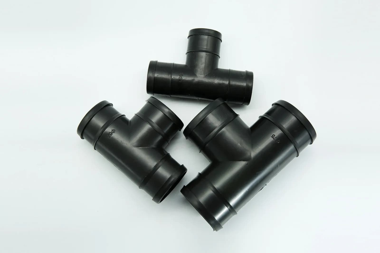
An irrigation valve manifold should supply each permitted combination of branches at its required flow and pressure while leaving a practical way to isolate and service the equipment. Count the water passing through each shared header section, then check the complete route to every branch outlet. Enough connection ports do not establish hydraulic capacity, and closely grouped valves do not automatically provide maintenance access.
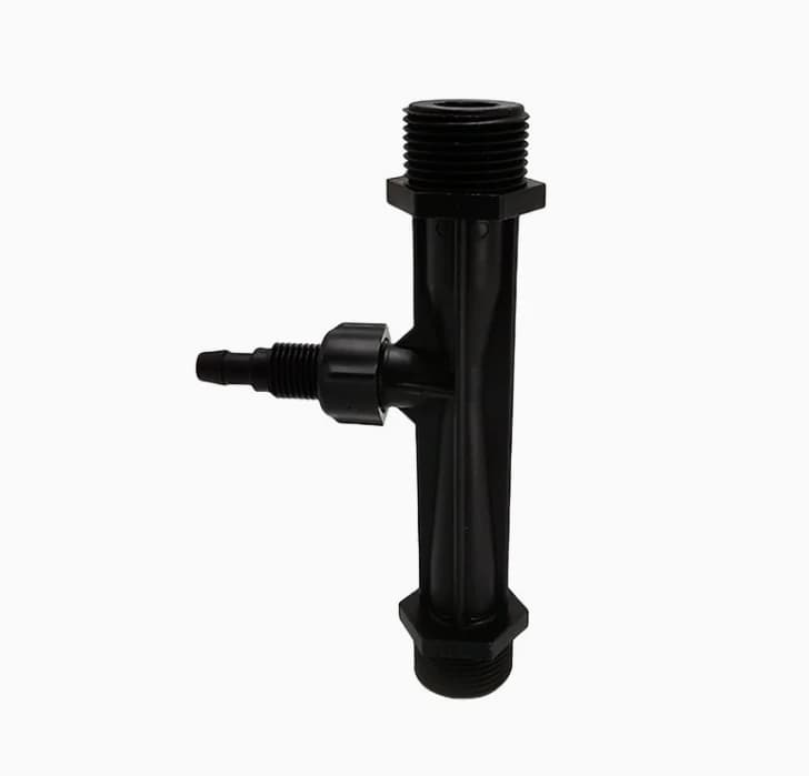
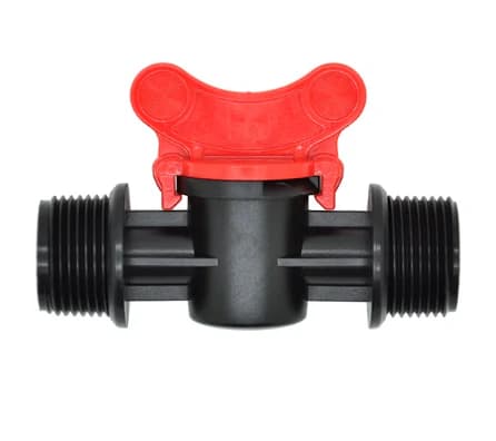
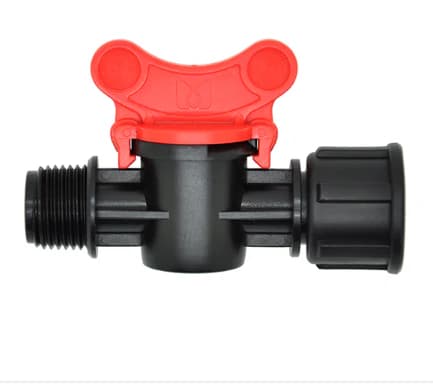
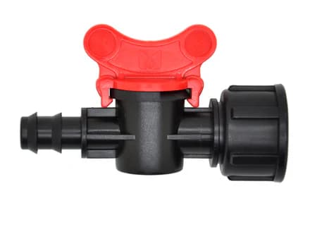
Tee-shaped irrigation fittings illustrate branch connection paths. These separate parts are not an assembled valve manifold or evidence of its hydraulic capacity. Photo: IrriNex.
The useful deliverables are a labeled connection drawing, an operating-combination table and a removal plan. The original example below shows how an additional branch can reduce the head available to existing branches even when their own requested flows remain unchanged. All dimensions, flows and losses in the example are hypothetical.
1. Give every connection and isolation boundary an identity
Start the drawing at the manifold's defined supply boundary. Show the common isolation provision, supply measurement point, header sections, branch takeoffs, control valves, permitted removable connections and downstream tie-ins. Mark any pilot supply, pilot drain, bypass or second water source that could change the isolation boundary. Include planned expansion ports, with their current capped or isolated condition.
For a simple example, label the supply point S and three successive takeoffs T1, T2 and T3. Header section H1 connects S to T1; H2 connects T1 to T2; H3 connects T2 to T3. Branch A leaves T1, B leaves T2 and C leaves T3. Each branch then passes through its specified branch assembly to a defined outlet measurement point.
The routes are therefore S–H1–A, S–H1–H2–B and S–H1–H2–H3–C. These labels describe a connection diagram, not a scale drawing or a ready-to-install piping detail. The equipment drawing must also locate the actual isolation devices, supports, drains and access needed by the selected components.
Use the irrigation valve function guide to distinguish isolation, zone switching and pressure control. One device should not be assigned all three duties unless its supplied configuration and operating procedure support them. A remote off command is not automatically the isolation required for dismantling a branch.
2. List operating combinations before sizing the header
Record each branch's required flow and minimum pressure at a clearly defined point. Include any required maximum pressure and the operating range of downstream regulators, filters or emitters. Branches serving different crops or areas need not have equal flows. Balancing means meeting their separate design duties, not making every gauge or flow display identical.
List which branches may operate together, including approved changeover overlap, flushing, filter backwash and other simultaneous demands connected inside the supply boundary. A controller with enough station addresses does not establish that the common header or water source can supply them together.
The FAO system-design chapter explains why flow decreases along a manifold as outlets take water and why this changes friction-loss calculations. Its multiple-outlet factors have particular assumptions. For a short manifold with unequal branch demands and unequal spacing, calculate the actual segments rather than applying one factor without checking its basis.
In the example, branches A, B and C request 4, 6 and 8 m³/h respectively. With all three operating, the supply and H1 carry 18 m³/h. H2 carries the remaining 14 m³/h after A's takeoff, and H3 carries 8 m³/h after B's takeoff. Applying 18 m³/h to every segment would describe a different flow path.
| Header section | Branches supplied downstream | Flow calculation | Section flow |
|---|---|---|---|
| H1 | A, B and C | 4 + 6 + 8 | 18 m³/h |
| H2 | B and C | 6 + 8 | 14 m³/h |
| H3 | C | 8 | 8 m³/h |
Repeat that map for the other permitted combinations. A common section may carry less flow when one branch stops, while the source pressure also changes. Keep supply performance and downstream demand in the same scenario; do not combine the best supply reading from one condition with the largest demand from another.
3. Add losses along each branch's actual route
The EPA's EPANET network-model documentation treats junction flow conservation and link head-loss relationships together. It also distinguishes prescribed demand from pressure-dependent delivery. That distinction matters when a calculation reveals insufficient pressure: an assumed target flow is not proof that the field receives that flow.
Use a common elevation datum and consistent units. Compare pressure readings only after considering tap elevations and the applicable velocity terms. Fitting losses also depend on the route through a junction. Allocate the run path and branch path consistently, and do not count the same tee loss in both a header allowance and a branch allowance.
For the following simplified nodal calculation, assume all nodes are at elevation zero, all pipes remain full, and velocity-head differences at the junctions are omitted. Assume supply head at S is fixed at 32 m of water for the scenarios examined. This is a modeling boundary, not a claim that a real pump holds constant head as demand changes.
At the flows in the first table, assign hypothetical header losses of 3 m in H1, 2 m in H2 and 1 m in H3. Assign complete branch-route losses of 2 m for A, 3 m for B and 4 m for C, including the selected branch assembly and its allocated fittings. These are example inputs, not losses inferred from connection diameter or a manufacturer's valve curve.
Assume the required minimum heads at the defined branch outlet nodes are 24 m for A, 22 m for B and 20 m for C. These are project inputs at the stated nodes, not recommended emitter pressures. The supply boundary is already downstream of any losses outside this modeled manifold, so those losses are not subtracted again. Use the whole-system irrigation pressure budget to connect that boundary with the pump and final emitters.
| Branch | Head calculation from S | Available outlet head | Assumed minimum | Difference |
|---|---|---|---|---|
| A | 32 − 3 − 2 | 27 m | 24 m | +3 m |
| B | 32 − 3 − 2 − 3 | 24 m | 22 m | +2 m |
| C | 32 − 3 − 2 − 1 − 4 | 22 m | 20 m | +2 m |
All three pass this stated minimum-head screen. The positive differences are not a complete design reserve: uncertainty, other operating combinations, maximum pressures, equipment ranges and transients still require evaluation. Nor does equal head margin mean equal irrigation demand.
Where actual valve coefficients are available, the Cv and Kv pressure-loss guide helps establish a valve contribution at the relevant position and flow. Keep that calculation within the complete branch route instead of treating it as the whole manifold loss.
4. Recheck existing branches when adding an outlet
Now consider a proposed fourth branch D beyond T3 requesting another 4 m³/h. Hold A, B and C's requested flows fixed solely for a feasibility screen. The three existing header sections would need to carry 22, 18 and 12 m³/h. Even before specifying D's own downstream pipework, those increased shared flows change the losses seen by the original branches.
For this arithmetic exercise only, assume each existing header section follows a fixed-resistance relationship h = RQ² between the two scenarios. Therefore its new loss equals its original loss multiplied by the square of the new-to-original flow ratio. This is an assumed model, not a universal statement that a real pipe's friction factor or every fitting coefficient stays constant.
| Section | Required new flow | New-loss calculation | New head loss, rounded |
|---|---|---|---|
| H1 | 22 m³/h | 3 × (22/18)² | 4.48 m |
| H2 | 18 m³/h | 2 × (18/14)² | 3.31 m |
| H3 | 12 m³/h | 1 × (12/8)² | 2.25 m |
Using unrounded intermediate results and the same hypothetical 32 m supply head, A would have about 25.52 m at its outlet. B would have about 21.21 m, below its 22 m minimum by 0.79 m. C would have about 17.96 m, below its 20 m minimum by 2.04 m. Their own branch losses were held fixed because their requested flows were held fixed in this screen.
The proposed combination therefore fails the stated minimum-head requirements for B and C. These values do not predict actual delivery in a pressure-dependent field network. A full solution may produce different flows and supply head. Branch D's own route and required head also remain unspecified, so this is not an approval of D.
Evaluate alternatives such as changing permitted combinations, revising the common header or reconsidering the supply arrangement through the responsible designer. Merely adding a connection port does not supply the missing head. Increasing source pressure also needs a complete review of maximum pressures, closed-valve conditions and equipment limits.
5. Adjust branch duty with the right control function
First check whether each branch has sufficient available pressure and an appropriate operating range. A balancing restriction can dissipate excess head in a branch that has it; it cannot create head in an under-supplied branch. Restricting one branch also changes the network, so any adjustment must be evaluated against all affected duties.
A fixed manual setting need not maintain a constant downstream pressure when other branches open or close. A pressure-regulating arrangement has its own minimum differential, flow range and operating behavior. Use the pressure-reducing valve operating-range guide when that function is required.
Specify measurement points that distinguish common-header conditions from branch losses. Pair an appropriate header measurement with branch inlet or outlet measurements and flow evidence where needed. Record the active combination, source condition and valve settings alongside the readings. A single gauge observed during one favorable combination is insufficient for a manifold with several operating states.
6. Design the removal path as well as the installed position
For each replaceable component, show which approved joints separate and which pipe sections remain supported when it is removed. Include the space needed to undo a connection, withdraw a part, lift a bonnet or reach a control. A union or removable spool can help only when its orientation and available movement suit the actual service operation.
The Western Washington University irrigation specification includes access for valve operation and maintenance, valve identification and record drawings. It is an institutional project specification, not a universal agricultural installation rule. Use those documented service needs as questions for your own drawing, without importing its brands, clearances or construction details.
Identify every possible pressure source on both sides of the proposed service break. A closed branch control valve may leave the common header pressurized; another connected supply can also invalidate the assumed isolation. Plan isolation, prevention of unintended restart, drainage and verification of depressurization through the installation's approved procedure before intrusive work.
Provide independent support and restraint appropriate to the design. The remaining pipework should not rely on a component being removed to carry its load. Do not use a connection nut to pull misaligned pipework into position. The installation drawing should resolve alignment, support and thermal movement using the specified component system.
7. Hand over a manifold record that survives expansion
Label the actual branch, its valve and the controller station consistently. Keep the connection drawing, permitted operating combinations, branch flow and pressure requirements, valve settings, measuring points and service boundaries together. Identify unused ports so a later installer cannot mistake an available fitting for an approved additional irrigation demand.
Commission the permitted combinations under an agreed plan and record the results at the specified points. Verify both individual operation and the required simultaneous cases. Check that stopping or isolating one branch produces the intended result elsewhere and that any necessary pump or injection permissions remain effective. Do not create an abnormal pressure event merely to explore an unapproved combination.
For an expansion, update the shared-section flow map before ordering another valve. Recheck source capacity, header losses, branch limits, electrical capacity, access and isolation. Retain the previous operating record and document which assumptions changed. This makes the manifold a maintainable part of the farm's system rather than a collection of ports whose capacity is guessed.
8. Questions about irrigation valve manifolds
Should every branch have the same flow?
No. Each branch should meet its own design duty. Different areas, emitters and operating methods can require different flows and pressures. Compare each measured result with its specified requirement rather than forcing equal readings.
Can I add a zone if the manifold has a spare outlet?
A spare outlet establishes a possible connection point only. Recalculate the affected header sections and source duty for the proposed operating combinations, then verify equipment limits, controls and service access before enabling the new zone.
Does a removable connection make live maintenance safe?
No. Removability describes how parts separate after the correct isolation and verified depressurization. It does not isolate the water source, prevent a remote restart or protect against another connected supply.