Irrigation Valve Commissioning: Record Setpoints, Response Times, and Shutoff
Irrigation valve commissioning should leave a record that another technician can reproduce and an operator can use. For each required function, connect the approved requirement to the installed configuration, test conditions, measured result and acceptance decision. A pressure setting, a successful opening command or a signed installation checklist alone does not demonstrate the complete valve duty.
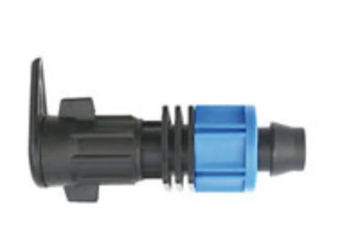
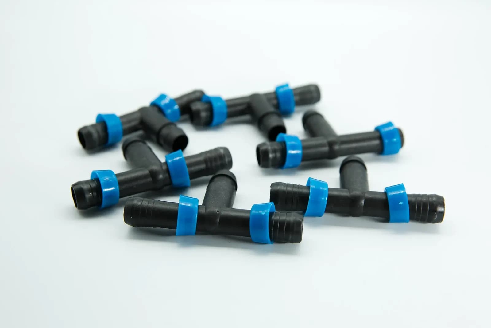
Black T-shaped irrigation fittings with blue connection rings, illustrating branch-connection identification. This product photograph does not show a valve or a commissioning test. Photo: IrriNex.
The practical output is an acceptance sheet with linked test files and a defect register. This article develops that record for agricultural irrigation valves. All numerical requirements, error bounds and observations below are invented teaching examples, not equipment ratings, recommended tolerances or results from an IrriNex installation.
1. Turn the required valve functions into testable rows
Begin with the approved hydraulic design, valve and pilot identification, actuator details and control sequence. Record the document revisions used. Confirm which functions the supplied assembly must perform: ordinary shutoff, downstream regulation, upstream pressure support or another specified duty. Do not assign a regulating requirement to a manual isolation valve merely because both appear on the same drawing.
The September 2020 GSA Commissioning Guide, particularly its test-record and follow-up discussion on pages 28–29, connects expected performance, observations, test conditions and issue resolution. It concerns federal buildings. The transferable practice here is traceable functional verification; its contracts, occupancy rules and building-specific test obligations are not agricultural requirements.
| Required function | Requirement to obtain before testing | Evidence to retain | Scope of the decision |
|---|---|---|---|
| Pressure regulation, if specified | Target, allowable band, approved flow cases and observation window | Actual configuration, flow, inlet conditions and downstream pressure record | Regulation in the tested cases |
| Opening or closing response | Defined initiating event, observable endpoint and allowed interval | Time-aligned event record and measurement limitations | The defined response under the stated starting conditions |
| Shutoff | Test boundary, pressure conditions, stabilization rule and permitted residual flow | Measured volume or flow with instrument capability | Compliance with that shutoff criterion |
| Specified interruption response | Approved method, starting state and required resulting condition | Supervised test or accepted simulation and unresolved limits | Only the interruption cases actually verified |
Use the pressure-regulation operating-envelope worksheet to establish valid duties before commissioning. This acceptance sheet records whether those duties were demonstrated. It does not create a missing minimum-flow specification or authorize operation outside the supplied valve's limits.
2. Record the conditions that make a result repeatable
Give each test a unique identifier and record its date, valve tag, location, operator, witness and configuration revision. Mark whether it is an initial test or a retest. Attach the relevant drawing with pressure taps, meter position, pilot discharge, bypasses and other connected supplies identified. Keep the original observations alongside any later corrections.
Record the source and pump state, active zones, filter condition, initial valve state and available actuator supply. Describe the steady operating condition or the deliberate transition being tested. A different source level, simultaneous zone or pilot adjustment can change the result even when the displayed setpoint is unchanged.
University of Arizona Extension's August 2025 irrigation-maintenance publication describes pressure and flow checks at startup and comparison with design or benchmark values. That supports retaining measured operating conditions. Its particular sampling recommendations, percentage bands and maintenance treatments are not universal valve-acceptance criteria and are not adopted here.
For every instrument, record identity, range, resolution, calibration or verification evidence and the applicable measurement uncertainty or error assessment. Include sampling interval and time alignment where needed. Distinguish a display's digit resolution from its accuracy. Identify gauge-pressure references and tap elevations; measurements at different elevations are not automatically interchangeable.
Confirm readiness before functional trials: correct installed assembly, completed cleaning and flushing, usable test ports and the approved protection sequence. Use suitable water-only procedures within the system's permitted conditions. Do not create a damaging surge, defeat an interlock or open a pressure-containing connection to complete a checklist. An unavailable prerequisite is a recorded hold point.
3. Preserve both the original and the accepted setpoint record
A target entered in a controller or marked on a pilot is a setting. The measured downstream pressure is an observation. Retain both. Specify the measurement location, valid demand case, settling rule and observation period before deciding whether the observed pressure meets the requirement.
Consider an original example requiring downstream gauge pressure between 190 and 210 kPa, inclusive, around a 200 kPa target. These limits are hypothetical. Suppose the complete pressure record for a defined steady-duty test has the measured extremes below. The instrument and sampling method are assumed suitable for the variation being assessed; the project's measurement decision rule remains part of final acceptance.
| Test and configuration | Recorded target | Measured pressure range | Numerical comparison |
|---|---|---|---|
| Initial test, configuration A | 200 kPa | 194–214 kPa | Maximum exceeds the upper limit by 4 kPa |
| Retest after an authorized correction, configuration B | 200 kPa | 196–204 kPa | Measured range lies within the stated band |
The first record has deviations from target of −6 and +14 kPa. The retest has deviations of −4 and +4 kPa. Keeping the same target did not produce the same result. Record the actual authorized correction and changed configuration; these invented observations do not identify what caused the initial excursion.
A result near a limit needs the agreed treatment of measurement uncertainty. Passing the numerical comparison alone is not full acceptance. Retain the raw trace, instrument assessment and review decision. Do not replace the original failed record with the final screenshot or describe a new setting as verified before the affected tests are repeated.
Use the full required record rather than a convenient average. A slow logger cannot certify the absence of a rapid pressure peak. Steady regulation, startup behavior and required transient protection need the appropriate evidence for each function. The acceptance sheet identifies which of those requirements the test actually covers.
4. Define response time before starting the clock
State the initiating event and endpoint in the test sheet. An initiating event might be a verified local command transition. An endpoint might be arrival at a specified mechanical position or completion of a defined hydraulic settling condition. If the requirement starts when an operator presses a remote button, include that earlier event and the communication path instead.
Where a hydraulic endpoint requires pressure to remain in a band, specify the dwell interval, sampling method and whether reported response time ends at initial entry or at completion of the dwell. Those definitions produce different durations. Record enough of the trace to apply the agreed definition without reconstructing it from memory.
Suppose a separate hypothetical requirement permits no more than 25 s from the verified start event to its fully defined endpoint. Three measured runs give 23.9, 24.2 and 26.0 s. Assume a validated total timing-error bound of ±0.4 s for each duration, including endpoint detection. Their upper possible durations are 24.3, 24.6 and 26.4 s.
For this example, acceptance requires each run's upper possible duration to stay within 25 s. The first two pass; the third fails even at its lower possible duration of 25.6 s. Yet the average measured duration is (23.9 + 24.2 + 26.0)/3 = 24.7 s. That favorable average cannot replace a requirement applying to every run. Three trials also do not establish a long-term failure rate.
Specify required cases and repetitions from the project needs. Test minimum or changed operating conditions only when the approved plan allows them. The irrigation valve types guide provides the function-selection context. Hydraulic closure and surge still need their own design assessment; a commissioning time limit cannot substitute for it.
5. Give shutoff its own measurable acceptance boundary
Write down what the shutoff measurement includes. An inlet meter may include a pilot drain, bypass or another outlet. Downstream dripping may come from stored lateral water. The test arrangement must separate or explicitly account for these paths before a result can be attributed to the required valve function.
For a separate hypothetical test, assume an approved arrangement measures only residual water crossing the required shutoff boundary. Other supplies and flow paths are excluded, storage effects have stabilized under the specified procedure, and gauge pressures are maintained at the specified test taps: 300 kPa upstream and 50 kPa downstream. These are invented test conditions, not a prescribed field arrangement.
Suppose a suitable measurement records 1.2 L during a 10-minute window. The average residual rate is 1.2 ÷ 10 = 0.12 L/min, equivalent to 7.2 L/h if maintained. Assume the total volume error is bounded by ±0.2 L and timing error is negligible for this example. The possible average rate is therefore 0.10–0.14 L/min.
If the hypothetical project permits at most 0.15 L/min under those conditions, the upper bound of 0.14 L/min passes that average-flow criterion. It does not establish zero leakage, a universal leakage class, maintenance isolation or compliance with a backflow-device test. The criterion must come from the actual project and equipment requirements.
A meter outside its valid low-flow range cannot support this calculation merely because its total display stayed still. Where continuing water needs diagnosis, use the irrigation valve maintenance guide as a starting record of condition and service. Commissioning records the acceptance outcome and supporting evidence; detailed component diagnosis follows when required.
6. Count accepted tests without hiding deferred or invalid results
Open an issue for every failed requirement, missing prerequisite or unresolved acceptance decision. Name the responsible person and required next action. Keep the original result visible. A repair invoice, adjusted setpoint or acknowledged alert does not establish that the previously failed function now meets its requirement.
Consider a separate hypothetical package containing 8 required test records for one assembly. The test list and counting unit were fixed before work began. Each record represents a defined test case, not a valve population or a measure of hydraulic reliability. The initial review gives the following status.
| Status | Count | Required next step |
|---|---|---|
| Passed with valid evidence | 5 | Retain the accepted record and review whether later changes affect it |
| Failed requirement | 1 | Correct the demonstrated problem and retest the affected case |
| Invalid evidence because of a recording fault | 1 | Restore the measurement method and repeat the test |
| Deferred because the required supply condition was unavailable | 1 | Assign the missing test and any necessary operating restriction |
Accepted completion is 5/8 = 62.5%. Dividing 5 by only the 6 valid completed records gives about 83.3%, but that is a different denominator and hides the invalid and deferred work if presented as package completion. Neither percentage is a valve reliability estimate, and a high completion percentage cannot excuse an unresolved critical requirement.
Suppose approved correction and retesting subsequently resolve both the failed and invalid records. Assume the review confirms that the other accepted tests remain applicable. Completion becomes 7/8 = 87.5%; the unavailable supply case is still deferred. Do not mark the entire proposed operating scope as verified. The authorized release decision must state any limits while that case remains open.
For each closure, record the actual change, retest identifier, retained results and designated reviewer's decision. A pilot adjustment or configuration change can affect previously passing pressure, timing or shutoff checks, so review the retest scope. If the requirement itself changes, preserve its earlier revision and the authorized reason. Never quietly widen a tolerance after seeing an inconvenient result.
7. Hand over an operating record with explicit limits
Provide the accepted settings, configuration, tested duty cases, instrument records, raw files, completed decisions and remaining restrictions together. Show the operator where to find the approved normal and interruption sequences. Identify the person responsible for unresolved items and the conditions that trigger further verification.
Keep completed tests separate from the overall release decision. A valve can pass a normal-flow pressure test while another required function remains unverified. The person authorized to release the installation must see those limitations. Mark an untested seasonal supply condition explicitly instead of describing the valve as proven across its entire proposed range.
After an actuator replacement, pilot change, revised zone combination or source modification, compare the new arrangement with the accepted record. Review which previous results still apply. The pump and valve interlock record provides the related operating-permission context when the system sequence changes.
8. Frequently asked questions
Is a photograph of the pressure gauge enough?
It can support a recorded observation, but it needs the valve identity, tap location, operating conditions and instrument information. It cannot replace a required time history, response test or shutoff measurement.
Should every valve use the same acceptance tolerance?
No. Requirements depend on the intended function, supplied equipment, connected irrigation system and measurement capability. Agree the criterion and decision rule before testing; the numerical examples here are not default limits.
Can a corrected defect be marked complete immediately?
Record the correction immediately, then perform and review the affected verification. Close the issue when the required evidence supports acceptance under the documented conditions. Keep any deferred or excluded cases visible.