Technical2026-11-02
An irrigation pump minimum flow is an equipment operating limit, not the smallest amount of water a crop needs. When one small irrigation zone is open, the pump must still operate inside the flow, head and speed envelope approved for that exact pump. If zone demand falls below the applicable minimum, change the operating arrangement before allowing the schedule to run unattended.
The practical method is to obtain the selected pump's limits, list the measured demand of every permitted valve combination, and approve only combinations that satisfy both pump protection and irrigation delivery. A variable frequency drive may expand the usable range, but reducing speed does not automatically make any small flow acceptable. This guide addresses centrifugal irrigation pumps; positive displacement equipment requires its own protection design.
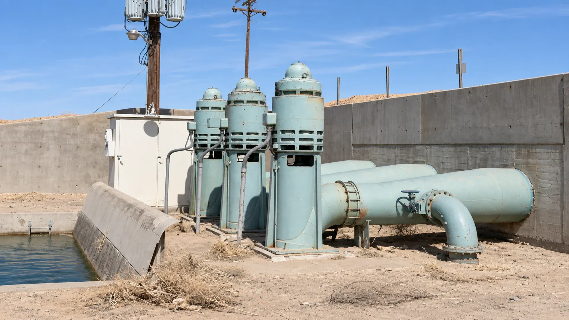
Photograph: David G. De Vries, Library of Congress / Historic American Engineering Record, HAER AZ-68-D-3, public domain. Real pumps at the Wellton-Mohawk Irrigation System; archival photograph lightly color restored with AI. The pictured installation is illustrative and is not the system used in the numerical example.
At sufficiently low flow, some centrifugal pumps develop damaging internal recirculation, vibration or excessive temperature rise. The point at which a particular mechanism becomes unacceptable depends on the pump and operating conditions. A pressure gauge can look steady while the pump operates outside its approved region. Conversely, a cycling pump may have a control or sensor problem without being below its hydraulic minimum.
Keep the following terms separate when speaking with the supplier:
Ask which limits govern the actual installation and whether any permitted transient differs from continuous duty. Do not select the smaller of two limits because it makes a schedule easier to run. The final envelope must satisfy all applicable restrictions. Our explanation of pump curves as irrigation zones change covers the head and flow relationship behind this comparison.
Record the pump model, serial or asset number, impeller diameter or stage configuration, motor, drive and curve revision. A catalog's largest flow number does not identify the installed duty. Ask for the approved flow range at every intended operating speed, together with head, efficiency, power and inlet requirements. Include any separate restrictions for bearings, seals, thrust, motor cooling and the drive.
For a variable speed installation, obtain the approved minimum speed and any excluded speed bands. Clarify whether the minimum-flow boundary changes with speed and how the controller is expected to enforce it. Affinity relationships can support preliminary comparisons; they do not replace supplier approval of a low-flow operating point, especially where static lift remains substantial.
Keep a dated selection sheet beside the controller settings. Identify the measuring location and the uncertainty of the flowmeter. A limit expressed as flow through the pump cannot be checked with a downstream meter that excludes a recirculation branch unless that branch is measured or otherwise verified. Likewise, a display in gallons per minute must specify US gallons or imperial gallons. The calculations below use US gallons.
Start with the smallest zone, then list every single zone and every simultaneous combination that the controller can request. Add filter backwash, lateral flushing, tank refill, manual operation and transitions between zones. Record valve identities, target outlet pressure, observed flow, permitted pump arrangement and required protection. A schedule editor should be able to tell why a combination is allowed.
Use emitter counts and rated discharge as a preliminary estimate, then confirm demand after the system stabilizes. Pressure-compensating outlets still have an approved pressure range; a blocked filter or partly closed valve can reduce actual flow. Measure clean and service-limit conditions where practical. Check the pressure budget from pump to emitter and use instruments that can resolve the pressure differences being assessed.
Hypothetical example: a pump selected for a 500 US gpm duty has an illustrative supplier minimum of 150 US gpm at the speed being assessed. The 150 value is an invented example, not a general percentage of rated flow. A different pump or speed may have a different boundary. Suppose measured zone demands at their required pressures are A = 82, B = 110 and C = 175 US gpm.
Q (m³/h) = Q (US gpm) × 0.227124; Q (L/s) = Q (US gpm) × 0.0630902. Thus 500 US gpm is approximately 113.56 m³/h or 31.55 L/s, and the illustrative 150 US gpm minimum is 34.07 m³/h or 9.46 L/s.
| Requested duty | US gpm | m³/h | L/s | Minimum-flow screening |
|---|---|---|---|---|
| A alone | 82 | 18.62 | 5.17 | Below 150; arrangement must change |
| B alone | 110 | 24.98 | 6.94 | Below 150; arrangement must change |
| C alone | 175 | 39.75 | 11.04 | Above the example minimum; other checks remain |
| A + B | 192 | 43.61 | 12.11 | Candidate only if simultaneous measured demand agrees |
| A + C | 257 | 58.37 | 16.21 | Check combined head, inlet capacity and pressure |
| B + C | 285 | 64.73 | 17.98 | Check combined head, inlet capacity and pressure |
The sums assume that each zone retains the pressure at which its demand was measured. Opening two zones changes friction losses and the operating point, so 82 + 110 = 192 US gpm is a planning estimate until verified together. Passing this table does not establish sufficient crop pressure, acceptable power or adequate suction conditions.
Record transient states separately. A valid A + B run may become invalid when B finishes first and A continues alone. Either coordinate their remaining water requirements, switch A to an approved smaller pump, or use another reviewed arrangement. Never extend B's irrigation merely to make the main pump comfortable if B has already received its agronomic allocation.
| Option | Useful situation | Required acceptance check |
|---|---|---|
| Combine compatible zones | Crop demand and watering windows overlap | Each zone gets its required depth and pressure without exceeding source or pipe capacity |
| Use a smaller duty pump | Small zones run frequently for long periods | The pony pump serves their flow and head inside its own approved envelope |
| Stage parallel pumps | Total demand spans several predictable ranges | Every operating pump meets its own minimum, including during staging |
| Use approved variable speed operation | The reduced-speed curve can meet the small duty | Flow, head, motor cooling and minimum speed all remain acceptable |
| Add storage and separate delivery | Source pumping and zone demand occur at different rates | Usable storage, refill cycles and the downstream delivery method meet the whole schedule |
| Install designed minimum-flow recirculation | The equipment arrangement requires a protected flow path | Route, valve, heat rejection and monitoring are engineered for the complete duty range |
A pony pump is a smaller pump selected for a real duty. The term jockey pump is also used for pressure maintenance, but an existing pressure-maintenance unit may be unable to irrigate a zone. Check the curve, motor duty and controls before assigning it sustained crop delivery.
Parallel staging requires more than dividing total station flow by the number of running pumps. Different curves, speeds, wear or check-valve behavior can produce unequal sharing. A strong pump can raise header pressure until a weaker pump contributes very little. Verify individual contributions with suitable measurements or a supplier-approved method, and avoid running an unnecessary pump just because total demand exceeds one pump's minimum.
Storage separates source rate from delivery rate only when the hydraulic arrangement really provides that separation. A tank feeding a suitably sized downstream pump can do this; a small pressure vessel attached to an oversized pump may only delay another start. Size usable volume from the imbalance over time and the approved run/stop constraints, allowing for level limits and irrigation reserve.
Closing a discharge valve increases system resistance and usually moves a centrifugal pump toward lower flow. It may reduce excessive delivery, but it does not by itself cure an already inadequate flow through the pump. Never use suction throttling as a casual way to regulate this duty.
For a designed recirculation branch, distinguish the pump flow from the useful crop flow. In a simple steady arrangement with no other branches, Qpump = Qzones + Qreturn. In the hypothetical A case, reaching 150 US gpm would require at least 150 − 82 = 68 US gpm, approximately 15.44 m³/h or 4.29 L/s, in the return branch. That arithmetic is a flow balance, not a valve size or a complete protection design.
The return destination, pressure drop, water temperature and availability of cooler replacement water matter. A short loop back to suction can accumulate heat. A return to a reservoir may alter inlet conditions or require substantial pipework. Fertigation creates additional questions about chemical concentration and whether treated water may return to the source. Do not route such water into an unapproved source or tank.
Specify how return flow is established and proven before demand becomes too small, and what happens if its valve fails shut. A pressure relief valve protects against a pressure condition; it is not automatically a minimum-flow device. An always-open bypass also consumes pumping energy whenever it carries flow, so compare measured seasonal energy and maintenance costs with a smaller pump or staging arrangement.
For each candidate remedy, plot the resulting operating point on the applicable curve and check both ends of its permitted range. Verify required pressure at the hydraulically disadvantaged outlet and the maximum pressure experienced by nearby valves, filters and laterals. Include dirty-filter loss and elevation changes without assuming that the discharge gauge represents every outlet.
Recalculate available net positive suction head for the lowest expected water level, highest relevant water temperature and actual inlet losses. Compare it with the selected pump's required NPSH and the supplier's required margin. Combining zones can improve a low-flow problem while increasing inlet losses enough to create a different problem. A flow reading alone cannot rule that out.
Check motor power over the new operating range, drive capability, minimum cooling requirements and check-valve opening. For a submersible motor, the relevant cooling flow past the motor can differ from the flow in the surface delivery pipe. Do not infer cooling adequacy solely from a surface meter. Confirm all such details with the equipment supplier.
Begin with an approved operating arrangement and calibrated instruments. Do not deliberately operate below a known limit to see whether the pump survives. Use safe signal simulation where appropriate to prove shutdown logic, with electrical work performed by qualified personnel. Any inspection requiring access to moving parts or pressurized equipment needs isolation and pressure release under the site's procedure.
| Record | What to capture | Reason |
|---|---|---|
| Identity | Date, operator, pump, curve revision, zone and valve combination | Connect the result to a reproducible configuration |
| Stable duty | Pump flow, zone flow, return flow if present, total head and outlet pressure | Separate equipment protection from water delivered to crops |
| Drive and motor | Speed, frequency, electrical power and relevant current | Confirm the approved drive and power range |
| Inlet | Water level, inlet pressure where applicable, temperature and filter condition | Document the inlet state behind the result |
| Mechanical observations | Noise, vibration, seal condition and specified temperature readings | Compare with supplier limits and the accepted baseline |
| Control behavior | Start/stop count, observed interval, alarm state and stage transitions | Identify short cycling or unstable control |
| Acceptance | Pass/fail, referenced limits, corrective action and responsible reviewer | Prevent an incomplete test becoming an approved schedule |
Observe long enough to capture stabilization and the complete control sequence, using the duration agreed for the equipment. Count starts during a stated interval rather than writing “cycles frequently.” Record what occurs as the last large zone closes, a filter enters backwash, a tank reaches its level limit and a communication link is lost.
Maintain a local pump stop function when no permitted water path remains. The sequence must coordinate valve motion and pump deceleration so protection does not create an unacceptable pressure transient. The related guide to pump and valve interlocks explains why a remote start command alone is not evidence that a flow path exists.
| Symptom | Possible explanation | Next action |
|---|---|---|
| Repeated starts and stops | Demand mismatch, sleep settings, leaking check valve or sensor error | Compare measured flow, pressure trend and controller events before retuning |
| High pressure with low flow | Restricted delivery path or operation near shutoff | Apply the approved stop response and verify valve state and pump curve |
| Flow falls as head rises | Growing resistance, filter loading or valve movement | Compare pressure across components and the zone ledger |
| Low motor current | Low hydraulic load, reduced speed or loss of water supply | Check speed, inlet condition and actual flow; current alone is inconclusive |
| Pressure control hunts | Sensor noise, poor tuning or an unsuitable operating region | Verify the hydraulic envelope and signal quality before changing gains |
| Return water heats up | Insufficient heat removal from the recirculation route | Stop under the approved procedure and review the return design |
| One parallel pump contributes little | Unequal curves, speeds or check-valve behavior | Check individual flow and revise staging before approving the combination |
Severe vibration, abnormal noise, loss of water or temperatures outside approved limits require the site's stop and inspection response. Do not repeatedly restart a tripped pump to finish a zone. An actionable alarm should name the zone, running pumps, measured flow, relevant limit and requested response; see irrigation alarm design for organizing those messages.
Store allowed combinations in the controller or the operator's approved procedure. Reject a small-zone request that has no valid pump arrangement. Link each allowed state to its setpoint, pump selection and stop response, and recheck the ledger when emitters are removed, zones are divided or flushing routines change.
Review trends after the first irrigation cycles and when source levels change seasonally. A lower-than-baseline flow may indicate blockage rather than reduced crop demand. If the required number of pumps changes between sectors, review the lead and lag pump control sequence before authorizing the revised schedule.
No. Use the value and conditions supplied for the selected pump. Capacity, preferred operation, stable flow and thermal flow are different concepts. A percentage copied from another installation is not a defensible operating limit.
Sometimes an approved reduced-speed operating point makes a return branch unnecessary, but that must be established from the complete selection. Static head, cooling and low-speed limits can prevent the pump from serving the smallest zone directly.
No. Pressure is only one measurement. Confirm flow through each running pump, its speed and inlet conditions, plus the other applicable equipment limits. Also verify pressure and delivery at the crop; a protected pump does not guarantee an adequately irrigated field.
The U.S. Department of Energy pumping-system sourcebook explains that low-flow internal recirculation can damage pumps, that manufacturers specify minimum flows, and that each pump in a parallel arrangement must satisfy its own limit. Its discussions of smaller duty pumps and control methods support comparing system arrangements rather than copying a universal setting.
The zone ledger, calculations and commissioning forms here are an editorial planning method. All numerical duties are hypothetical and are not measurements from the photograph or a tested IrriNex installation. Obtain the actual limits and final hydraulic design from the selected equipment supplier and the responsible irrigation designer.
Products relevant to this irrigation guide.
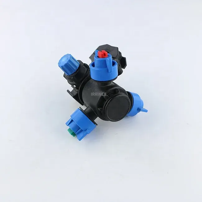
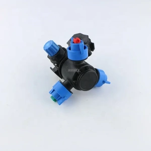
IRRINEX irrigation sprinkler. pressure: 2-4bar; flow: 0.33-9.24 L/MIN; Connection size: 25/32mm. This sprinkler is a water-distribution component for a selected irrigation layout. Use the listing's named sprinkler form and exact operating data when comparing configurations.
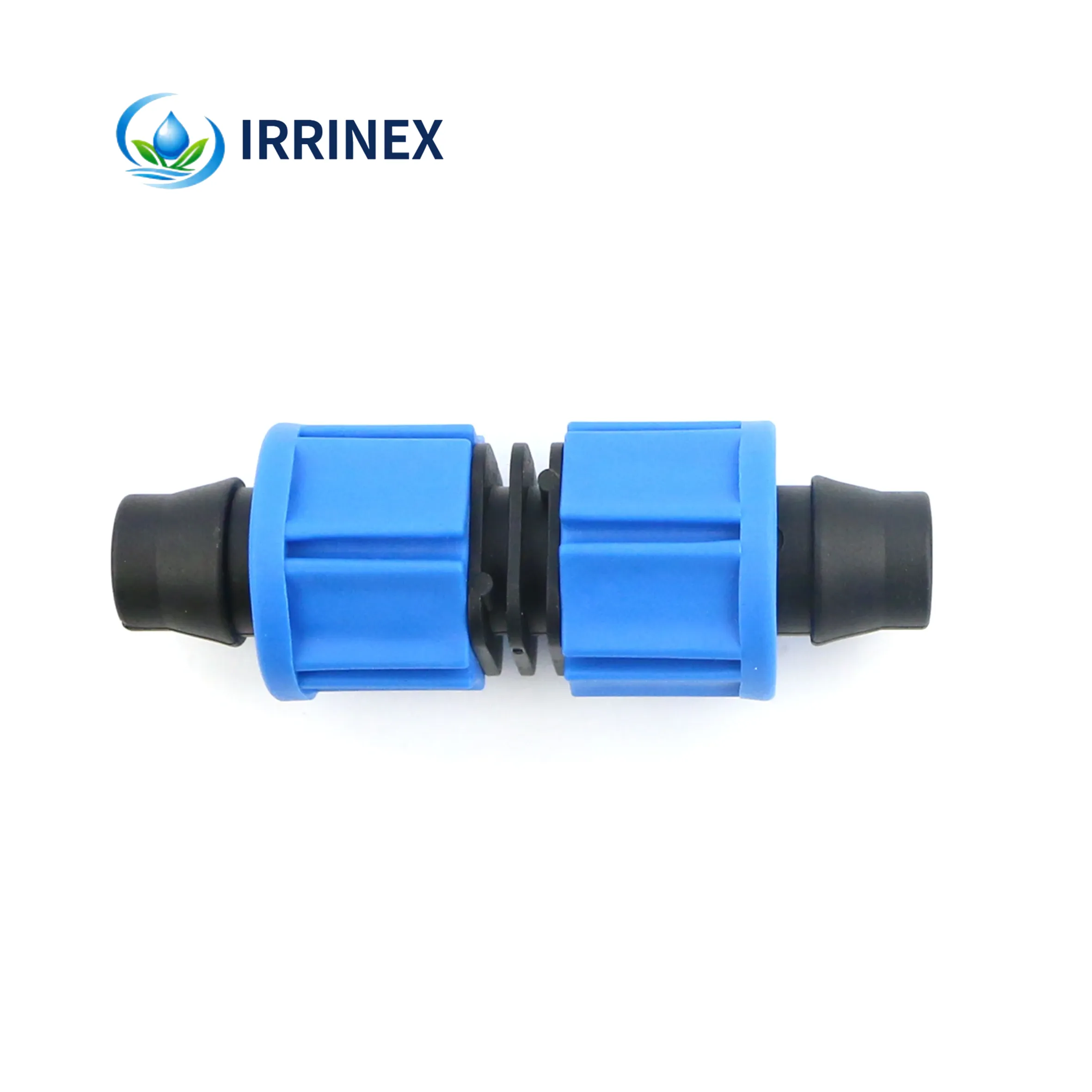
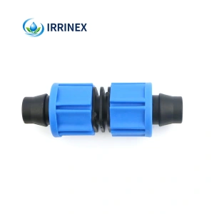
IRRINEX irrigation connection fitting. Size: 16mm; carton size: 47X36X53cm. A connection fitting joins or terminates selected irrigation components. Choose the named fitting form and match both sides of the connection.
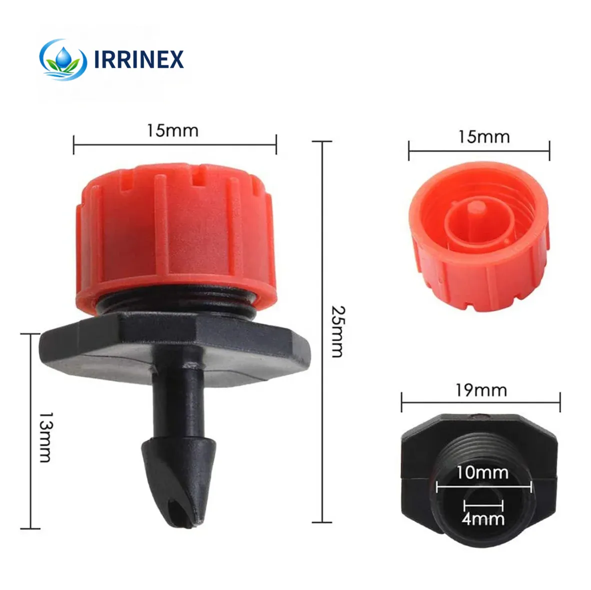
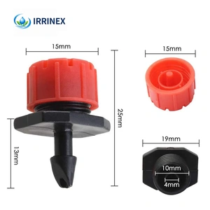
IRRINEX adjustable irrigation dripper. Diameter: 5mm; Flow rate: 0-90L/H; Wet Diameter: 0-0.4m; Working Pressure: 0.1-0.2Mpa. An adjustable dripper is selected for a point-watering arrangement. The chosen setting should be checked under the site's actual operating conditions.
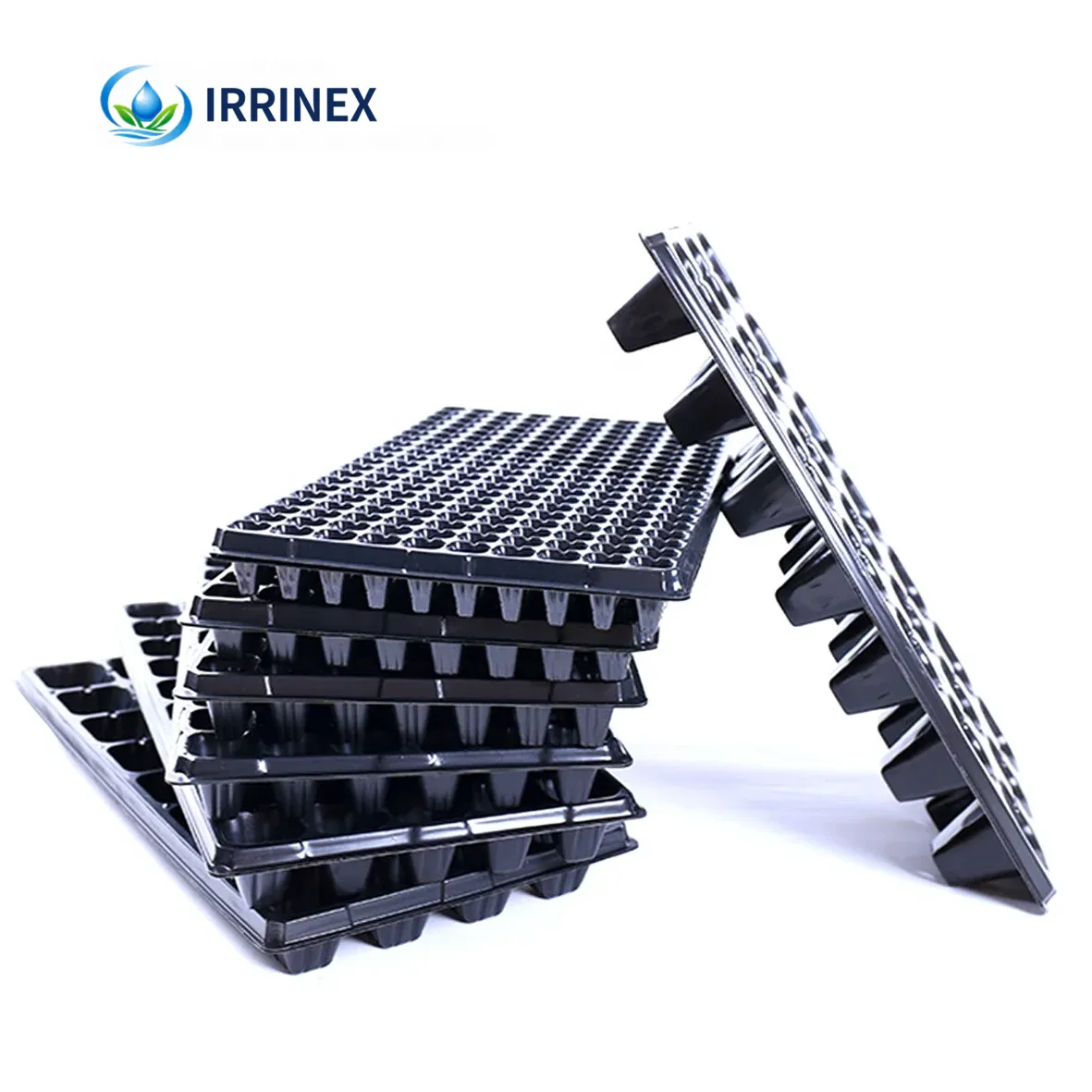
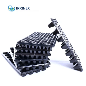
IRRINEX seedling propagation tray. sprinkler type: Vortex; type: Sprinklers; model number: 1-2. A seedling tray organizes propagation in separate planting cells. Cell count, tray dimensions and material should be checked for the selected configuration.