Irrigation Controller Station Capacity: Plan Expansion Before Buying Hardware
Irrigation controller station capacity must cover the outputs the farm will need, the combinations it will operate together and the electrical load those combinations create. Count installed and future functions, identify the permitted expansion modules, and check station, module and total-output limits separately. A controller advertised with enough station addresses may still be unable to start the required valves together.
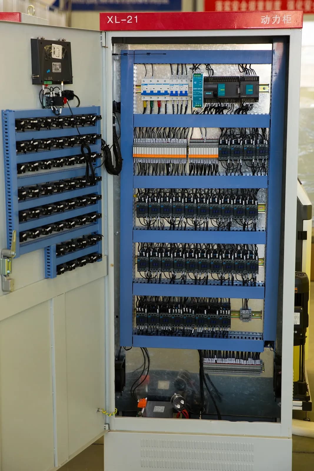
Open control cabinet with rows of electrical components and terminal wiring from the IrriNex equipment collection. The photograph does not establish the station capacity or AC load ratings assumed in this example. Photo: IrriNex.
This guide develops an expansion worksheet for agricultural irrigation controllers. The worked examples use invented station counts, module arrangements and electrical ratings. They illustrate the checks required before a purchase; they are not specifications for an IrriNex controller or another commercial product.
1. Count independently controlled functions before counting terminals
List every irrigation block that needs independent timing, then identify the physical valve and output that serves it. Two valves assigned to one output normally receive the same command, so adding a second coil does not create an independently scheduled zone. Conversely, an addressed device may provide several outputs, and its address count may differ from the number of valve functions it supports.
Add flushing valves, any approved filter-control functions and other required outputs. Specify whether each uses a general station channel, a dedicated auxiliary output or a separate compatible controller. Do not assume that every spare irrigation station can implement the required timing, interlocks and failure behavior for an auxiliary function.
List master valves and pump interfaces separately. A dedicated pump-start output controls an approved interface; it is not a connection for the pump motor. Sensor inputs, meter channels and communication ports also need their own capacity rows. A spare output terminal cannot substitute for a missing input type.
The AC, DC-latching and decoder controller comparison explains the architecture choices. For expansion, retain the exact controller, field-device and solenoid identities. Compatible voltage alone does not establish compatible output behavior or decoder communication.
2. Convert a farm growth plan into installed module capacity
Consider a hypothetical farm with 10 independently controlled irrigation zones. Its proposed growth plan adds four blocks, divides two existing zones into four smaller zones, and introduces two flushing functions that the assumed controller explicitly supports on general outputs. The owner also requests four unused general outputs as a project-specific reserve.
| Planning step | Change in required outputs | Cumulative requirement |
|---|---|---|
| Existing independent zones | 10 | 10 |
| Add four new blocks | +4 | 14 |
| Replace two existing zones with four independent zones | +2 net | 16 |
| Add two compatible flushing functions | +2 | 18 |
| Reserve four unused general outputs | +4 | 22 |
The subdivision adds two outputs, not four, because two existing outputs are replaced. The final operating-function count is 18; the purchasing requirement is 22 including the requested reserve. This distinction prevents both double-counting and accidental consumption of the spare capacity.
Assume the selected example architecture has eight base outputs, accepts modules of four outputs each and supports at most 24 general outputs. Assume the existing controller already contains one such module, giving 12 installed outputs. Meeting the 22-output requirement needs four modules in total: 8 + 4 × 4 = 24 outputs. Because one module is already installed, the expansion requires three additional modules, subject to exact compatibility.
After expansion, 24 − 18 = six physical outputs remain unused. Four satisfy the requested reserve, while two arise from the module increment. Do not describe all six as new approved irrigation functions: their future electrical, hydraulic and programming duties are still unspecified. This is a counting exercise, not evidence that an actual controller accepts the assumed modules.
Confirm the installed hardware revision, usable module bays, firmware support, regional model and any activation requirements against current documentation. A controller's maximum advertised count may require additional hardware or a different configuration. Keep the module part numbers and the existing-versus-new quantities on the quotation.
3. Separate total stations from simultaneous operation
For each permitted operating combination, count the active general outputs and identify additional master-valve, relay and auxiliary loads. Check whether the controller's simultaneous-operation limit refers to stations, physical coils, modules or all active outputs. Those units are not necessarily equivalent.
Review the way programs interact. Several saved programs do not necessarily run concurrently, and a controller that queues them can exceed the available irrigation window without exceeding an electrical limit. Include approved station overlap, manual operation, flushing and restart behavior. An unused address consumes no coil current until it is assigned and energized, but its proposed duty belongs in the expansion assessment.
Module-level limits can constrain a combination even when total controller capacity appears sufficient. Record which physical channels share each module or protected group. Reassigning channels is acceptable only within the manufacturer's supported configuration and the approved operating plan; it is not a way to bypass an output restriction.
4. Build an AC load sheet with starting and holding requirements
The following example concerns compatible conventional AC outputs. It does not apply directly to DC-latching pulses or a decoder power-and-communication path. Obtain the manufacturer's appropriate calculation method for those architectures instead.
For AC equipment, retain the units in the specification. Rice University's OpenStax discussion of AC power distinguishes RMS voltage and current from average real power, including the role of phase difference. Multiplying RMS volts by RMS amperes gives the apparent-power magnitude in volt-amperes, VA. It must not be relabeled as watts without the relevant power-factor information.
Assume all example field devices operate from the same nominal 24 V AC supply and that the listed current values are applicable manufacturer-provided RMS load allowances for the defined holding and starting intervals. The controller's documented field-load allowance is assumed to be 30 VA after its own internal consumption has been accounted for, valid for the assessed steady and starting conditions.
| Load | Holding current per device | Starting current per device | Connection in this example |
|---|---|---|---|
| Zone-valve solenoid | 0.12 A | 0.28 A | One coil per general output |
| Master-valve solenoid | 0.10 A | 0.24 A | Dedicated master output |
| Pump-interface relay coil | 0.06 A | 0.10 A | Dedicated compatible control output |
Also assume each general output permits 0.35 A, the relevant group of zone outputs permits 0.90 A combined, and no more than three general outputs may be active at once. For this exercise, the dedicated outputs individually support the listed loads and are additional to that three-output count. Every one of these limits is invented and must be replaced by the actual assembly's documentation.
Add current magnitudes as a conservative screening allowance for simultaneous loads on the same supply. This does not reconstruct their combined waveform or establish the transformer's transient behavior. Verify how the real manufacturer defines starting current, its duration, permissible overlaps and total capacity. A transformer nameplate alone may not state the power available to field valves after internal loads and output electronics are considered.
5. Check startup and overlap instead of only the steady total
With three zone coils holding, plus the master and relay holding, the summed allowance is 3 × 0.12 + 0.10 + 0.06 = 0.52 A. At the assumed 24 V, that corresponds to 12.48 VA. The zone-output group carries an allowance of 0.36 A, below the assumed 0.90 A limit.
| Proposed event | Zone-group current allowance | Total field current allowance | 24 V load allowance | Screening result |
|---|---|---|---|---|
| Three zones, master and relay holding | 0.36 A | 0.52 A | 12.48 VA | Within the listed numerical limits |
| Three zones, master and relay starting together | 0.84 A | 1.18 A | 28.32 VA | Within the listed numerical limits; other checks remain |
| Four zones, master and relay starting together | 1.12 A | 1.46 A | 35.04 VA | Exceeds group current, total VA and active-output count |
The three-zone startup calculation is 3 × 0.28 + 0.24 + 0.10 = 1.18 A. A steady-load calculation would miss most of that assumed starting allowance. Even this passing row does not establish correct field voltage, actual valve movement or permissible hydraulic operation. Those remain separate checks before the combination is accepted.
Now consider starting a fourth zone while three others, the master and relay are already holding. The summed allowance would be 3 × 0.12 + 0.28 + 0.10 + 0.06 = 0.80 A, or 19.20 VA. Although the overall VA allowance is below 30, four general outputs would be active. That still violates the assumed three-output limit. Passing one capacity check cannot cancel a failure of another.
Putting two identical zone coils on one output also needs its own review. In this example their holding allowance is 0.24 A, but their combined starting allowance is 0.56 A, above the assumed per-output limit of 0.35 A. It also removes independent control of the two valves. Do not use a shared terminal as an expansion shortcut.
Confirm the actual starting and holding voltage at the demanding field location using the approved design and a qualified installer's measurements. Cable routes, shared returns, joints, temperature and supply tolerance can affect operation. The station and common-wire test map provides the documentation framework without treating this load worksheet as a cable-sizing result.
6. Check the irrigation window and water supply alongside the electronics
Write a schedule for the expanded set of functions. Use the actual irrigation durations and permitted combinations, including any repeated cycles, required delays and flushing windows. The controller must be able to express that schedule and finish it within the available operating period. Extra stored start times cannot increase a pump's water output.
Confirm flow and pressure for each proposed simultaneous combination and transition. The crop-stage and substrate zoning guide explains why independently timed blocks can be necessary. Joining incompatible crop duties merely to reduce station count can defeat the original expansion requirement.
Use the pump and valve interlock record to document operating permissions. A sequence that reduces overlapping electrical starting loads must still preserve the required water path and protection behavior. Do not solve the VA worksheet by inventing an unsupported pump-start delay or disabling a protective function.
7. Request a quotation that includes the entire expansion
Provide the existing equipment list, phased output count, reserved functions, approved simultaneous combinations, field-load sheet, cable drawing and sensor requirements together. Request exact module, power-supply and interface references. Include the work required to label and verify each new function, migrate settings where applicable and update the operator's records.
At handover, verify physical station identity and the approved operating combinations, not just the controller's displayed station count. The University of Florida nursery irrigation checklist emphasizes checking controls and observing water delivery through startup, operation and shutdown. That field evidence complements the controller's electrical checks; it does not provide universal electrical capacity ratings.
Retain both occupied and reserved output assignments. Mark any future feature requiring an unavailable input, module or supply upgrade. Revisit the worksheet when coils, modules, zone boundaries or simultaneous schedules change. The useful purchasing decision is whether the complete supported configuration meets the farm's defined expansion, including the operating conditions under which it will be used.
8. Questions about irrigation controller station capacity
Does a 24-station controller operate 24 valves at the same time?
Not necessarily. Total addressable stations, simultaneous-output count, per-channel loading, group loading and total available power are separate limits. Read the exact configuration's documentation and include master-valve and relay loads where required.
How many spare stations should a farm reserve?
Derive the reserve from the expected additional functions and uncertainty in the growth plan. The four reserved outputs in this example are an owner's hypothetical requirement, not a universal percentage. Check module increments and the maximum supported configuration.
Can a larger transformer make an overloaded controller acceptable?
Only a manufacturer-approved power-supply configuration can be considered. Changing the transformer does not increase channel, module, terminal or software limits. An unauthorized substitution can leave the actual limiting component unchanged; review the complete controller and field circuit.