
Technical2026-11-01
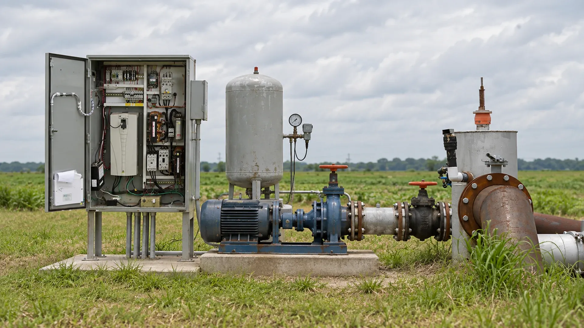
An irrigation booster pump should add only the pressure that a tank or shared supply cannot dependably provide at the active zone’s design flow. Measure the inlet while water is moving and neighbouring users are drawing, calculate the downstream pressure requirement, then select a pump whose curve covers every intended zone without starving the suction or overpressurizing the network. A static gauge reading alone cannot answer the sizing question.
This field guide separates pressurized boost, flooded suction and suction lift; builds a dual-unit pressure budget; and gives a commissioning matrix for constant-pressure control. The objective is stable emitter pressure and a protected water source, not the highest possible gauge reading.
A booster is justified when the minimum dynamic inlet condition plus the available source flow cannot meet the critical irrigation zone’s pressure and flow requirement. Typical triggers are a shared main whose pressure falls during peak withdrawals, an elevated or ground tank with level-dependent head, or a long transfer line feeding filters and pressure-regulated field blocks. First exclude restrictions: a fouled intake, undersized meter, partly closed valve or clogged filter can imitate an undersized source.
Compare measured field pressure with the pressure required by emitters, regulators, valves and treatment equipment. The irrigation valve selection guide helps identify which zone components create control and pressure requirements. If cleaning or opening a restriction restores the duty, a new pump would conceal the fault and could create excessive pressure when the restriction disappears.
The inlet category determines what pressure is available, how the pump starts and which failure can damage it. Record the category on the design sheet; do not combine assumptions from the three arrangements.
| Inlet arrangement | What the pump receives | Measure at worst demand | Essential protection |
|---|---|---|---|
| Pressurized shared main | Positive but variable pressure from a supplier, well header or farm network | Dynamic inlet pressure and available flow while competing users operate | Minimum-inlet permissive, supplier-approved backflow boundary and high-discharge trip |
| Vented tank, flooded suction | Water level above the pump centreline; gravity supplies the inlet | Minimum operating level, pipe loss and inlet pressure at maximum flow | Low-low level stop, restart deadband, overflow coordination and independent dry-run protection |
| Suction lift | Water surface below the pump; the pump must lift through a sealed suction line | Lowest water level, suction loss, altitude, water temperature and priming integrity | Foot/check valve as designed, screened intake, prime verification and NPSH margin |
A booster on a pressurized main is not automatically suitable for suction lift. The latter adds atmospheric-pressure, vapour-pressure, air-leak and priming limits. If a tank can be arranged above the pump, flooded suction usually gives the centrifugal pump a more reliable inlet than asking it to lift through a long line.
Install or temporarily connect a calibrated gauge or transducer close to the pump inlet, with a known elevation reference. Record static pressure before demand begins, then record pressure and flow after each planned zone stabilizes. Repeat while the tank approaches its minimum operating level or the shared supply is under its heaviest credible competing demand. A ten-minute quiet-period test may look excellent and still miss the design condition.
Log inlet pressure, outlet pressure, flow, source or tank level, active zone, filter differential, valve state and timestamp. A verified irrigation flow-meter total provides a useful cross-check on the instantaneous flow signal. Use one elevation datum and specify whether each pressure is gauge pressure. Trend data can reveal a collapsing source: inlet pressure that steadily declines at constant flow is not a control problem for the VFD to hide.
Calculate the discharge pressure the booster must create at each zone flow:
Required booster discharge = critical-zone operating pressure + elevation head + downstream friction and component losses
Required boost = required booster discharge − dependable dynamic inlet pressure
Use the lowest credible inlet, not the most favourable reading. Include clean and allowed-dirty filter loss, mainline and lateral friction, valves, check valves, fertigation equipment and elevation to the pressure-control point. Avoid counting the same elevation or component twice. The irrigation pump sizing and total dynamic head method provides the broader flow-and-head framework.
Suppose the critical block needs 35 psi at its inlet. The field is 18 ft higher than the booster, equivalent to about 7.8 psi, and measured downstream losses at design flow total 9.0 psi. Required booster discharge is therefore 35 + 7.8 + 9.0 = 51.8 psi, or approximately 3.57 bar and 36.4 m of water. For water near normal temperature, this example uses 1 psi ≈ 2.31 ft of head and 1 bar ≈ 10.2 m.
| Inlet case | Measured dynamic inlet | Required boost | Differential head | Interpretation |
|---|---|---|---|---|
| Low | 12 psi / 0.83 bar | 39.8 psi / 2.74 bar | 92 ft / 28.0 m | Curve and motor must cover this duty if it is a valid operating condition |
| Normal | 22 psi / 1.52 bar | 29.8 psi / 2.05 bar | 68.8 ft / 21.0 m | Likely normal speed after losses are verified |
| High | 32 psi / 2.21 bar | 19.8 psi / 1.37 bar | 45.7 ft / 13.9 m | VFD must slow without leaving its permitted range or causing cycling |
This is an example, not a universal setpoint. Repeat the calculation for every allowed zone combination because flow changes friction and the pump operating point. Add gauge uncertainty and accepted design margin transparently; never replace measurements with an arbitrary percentage.
Plot each required flow and differential head on the offered pump curve. Confirm that low, normal and high inlet cases remain inside the manufacturer’s acceptable operating range, with the selected impeller and actual speed limits. Check motor input at the lowest system resistance as well as the highest head. The pump and system curve guide explains why a valve change moves the operating point rather than simply subtracting a fixed pressure.
For a pressurized inlet or flooded tank, calculate net positive suction head available from the minimum absolute inlet head, atmospheric head, vapour pressure, suction losses and velocity terms, then compare it with pump NPSH required at the actual flow plus an engineering margin. For suction lift, evaluate the lowest water surface, warmest expected water, site altitude, strainer condition and air leakage. A positive gauge reading at one test condition does not prove adequate suction margin at peak flow.
The USDA NRCS Irrigation Pumping Plants chapter documents pump/system curves, centrifugal-pump selection, NPSH, VFD control and field evaluation. Use the current pump supplier’s certified curve and a qualified designer for the installed equipment; the public handbook supplies method, not a substitute model selection.
A VFD can vary pump speed to hold a discharge-pressure setpoint as zones open and inlet pressure changes. Put the control transducer at a hydraulically meaningful, serviceable location downstream of the pump and upstream of branches whose pressure must be controlled. A sensor at the pump cannot see every remote-zone loss; a remote sensor can improve endpoint control but needs reliable communication and sensible failure behaviour.
Commission proportional and integral response from trend data. Aggressive tuning makes speed and valves hunt; slow tuning leaves long low-pressure excursions. Set minimum and maximum speeds from the pump curve, motor cooling needs, minimum stable flow and source limits. Add an independent high-pressure switch or equivalent protective layer where the risk assessment requires it. The pressure controller must not override a low inlet, low tank, no-flow or dry-run trip.
At one tiny flushing line or after all zone valves close, the required flow may sit below the pump’s stable range. Options include a properly sized pressure tank for short draws, a minimum-flow bypass returned to an appropriate point, a smaller staged pump, or a stop-and-sleep function with verified restart criteria. Each option changes energy, temperature, cycling and water-accounting behaviour. Do not open a permanent bypass merely to keep an oversized pump comfortable without documenting where that water goes.
Coordinate demand permission with valve state. The pump and valve interlock procedure shows how to prevent a booster from running against closed demand. A restart should require both valid demand and healthy supply conditions.
A booster can lower pressure upstream and can change the consequence of a downstream contamination event. Obtain the water supplier’s and local authority’s requirements before final design. The accepted backflow assembly depends on water quality, hazard classification, fertigation, elevation, jurisdiction and connection arrangement. There is no universal device that can be prescribed safely for every farm.
Record the approved boundary, test access, isolation sequence and responsibility for inspection. Verify that the booster cannot pull the shared main below its permitted minimum. If chemigation or fertigation is connected downstream, integrate its enable signal, check devices and shutdown response with the site-specific approved design. A pump check valve controls reverse flow through the pump; it does not automatically satisfy public-health backflow requirements.
For a vented tank, define at least four levels: normal stop or high level for the fill system, normal operating band, low level warning, and low-low booster stop. Set restart above low-low by enough deadband to prevent rapid cycling. The restart level must reflect tank geometry, fill rate, pump flow and required reserve; it should not be copied from another installation.
Provide independent dry-run detection appropriate to the pump and source even when a level transmitter exists. Coordinate tank overflow/high level with the fill valve or source pump, and treat sensor disagreement as a fault. After a power return, the controller should verify level, inlet state, valve demand and pressure sensor validity before automatic restart. Store alarms with time, source level and pump state so a recurring shortage can be distinguished from a sensor failure.
Calibrate instruments before testing and use controlled valve changes. Record inlet and outlet pressure, flow, speed, motor current or power, tank level and alarms for every row. Acceptance limits must come from the hydraulic design, approved source constraints, certified pump data and local electrical requirements.
| Test condition | Field action | Expected response | Evidence to retain |
|---|---|---|---|
| One normal zone | Open one representative block and stabilize | Pressure settles without hunting; pump remains in allowed range | Inlet/outlet pressure, flow, speed and current trend |
| Multiple zones | Open the largest approved combination | Critical point remains adequate without violating source limit | Remote and station pressure plus flow |
| Minimum inlet | Test or safely simulate the approved minimum supply | Duty is met or the inlet permissive stops the pump before damage | Trip threshold, delay and restart sequence |
| Tank low-low | Lower or simulate level through a controlled test input | Booster stops, latches or waits as designed, then respects deadband | Level values, alarm, stop and restart timestamps |
| Closed demand | Close the final zone under the designed sequence | Pump sleeps or stops without pressure spike or rapid cycling | Peak pressure and number of starts |
| Pressure-sensor loss | Use the approved test method to remove or invalidate signal | Safe fault response; no uncontrolled acceleration | Fault code, final speed and shutdown state |
| Power recovery | Restore power after a documented outage test | Controller rechecks demand and every permissive before restart | Boot sequence, retained settings and valve state |
| Suspected fault | Distinguishing evidence | Next safe check |
|---|---|---|
| Inadequate inlet supply | Inlet pressure or tank level collapses as flow rises | Compare source recovery and competing-demand log with design minimum |
| Clogged intake or filter | Pressure differential rises across one component | Isolate, inspect and clean under the approved procedure |
| Leaking check valve | Pressure decays or reverse flow appears after stop | Isolate sections and verify valve closure without assuming the pump is leaking |
| Bad pressure transducer | Controller value disagrees with a calibrated local gauge | Check impulse port, wiring, scaling and calibration |
| Oversized pump | Minimum speed still gives excess head or repeated short cycling | Plot the low-flow duty and evaluate smaller/staged equipment |
| Unstable PID tuning | Pressure and speed oscillate with steady inlet and demand | Trend signals, verify sensor placement, then retune methodically |
| Downstream restriction | Outlet pressure is high while field flow and remote pressure are low | Walk valves, filter, regulator and pipe sections to locate the loss |
Change one condition at a time and preserve the before-and-after trace. Raising the setpoint can temporarily mask a blocked filter or failed sensor while increasing stress elsewhere.
Only when the supplier and local authority permit the connection and the design respects minimum inlet pressure, available flow and the approved backflow boundary. Measure the main under concurrent demand and program the booster to stop before it depressurizes the supply beyond the accepted limit.
Constant-pressure irrigation normally regulates a defined downstream pressure, while inlet pressure acts as a permissive or limiting signal. The exact sensor locations follow the hydraulic control point and source agreement. One transducer cannot represent every remote zone unless measured losses are predictable.
No. A pressure tank stores a limited volume and can reduce starts during small draws; a VFD changes pump speed over a flow range. Either, both or neither may be appropriate after the demand pattern and pump operating envelope are calculated.
Keep the pressure budget, source agreement, approved backflow design, pump and system curves, NPSH calculation, instrument calibrations, VFD parameters, permissive setpoints, commissioning trends, alarm tests and as-built sensor locations. These records make later diagnosis auditable.
Compare simultaneous inlet pressure, outlet pressure and flow before changing the setpoint. A falling inlet points toward source limitation; a normal inlet with weak outlet suggests pump or control performance; a strong outlet with weak remote pressure points toward downstream loss.
Products relevant to this irrigation guide.

IRRINEX irrigation system offering. Size: Diameter 16mm; Flow rate: 1.38-4L/H; Thickness: 0.2-1.0mm; Working pressure: 0.5Bar~2Bar. An irrigation system offering should be configured around the intended site and crop. Listing scope does not establish a complete bill of materials or guarantee area coverage.
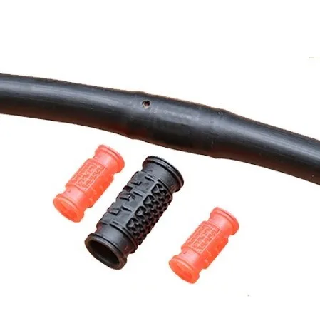
IRRINEX irrigation pipe or hose. Diameter: 12mm 16mm 20mm; Wall thickness: 0.6mm~1mm; Flow rate: 2-4L/H. Pipe or hose conveys water between irrigation components. Confirm the actual line type and dimensions before selecting connections or planning an installation.

IRRINEX irrigation dripper. Flow rate: 1.5L/H; Pressure: 0.05-0.2Mpa. A dripper places a selected water outlet in a drip-irrigation arrangement. Match the exact outlet configuration to the tubing and the documented operating conditions.

IRRINEX Venturi fertilizer injector. Diameter: 32mm 50mm 63mm; Max pressure: 8 Bar. A Venturi injector is used to introduce a liquid feed into irrigation water through a suitable injector arrangement. Select the connection and confirm the operating conditions needed for the exact injector.

