Irrigation Automation Retrofit: Connect Existing Valves Without Replacing Everything
An irrigation automation retrofit can retain existing valves when their condition, hydraulic duty and control interface are suitable for the proposed system. Some assemblies can remain unchanged, others need a documented conversion, and some require replacement. Identify those categories before buying a controller or promising that every block can be automated.
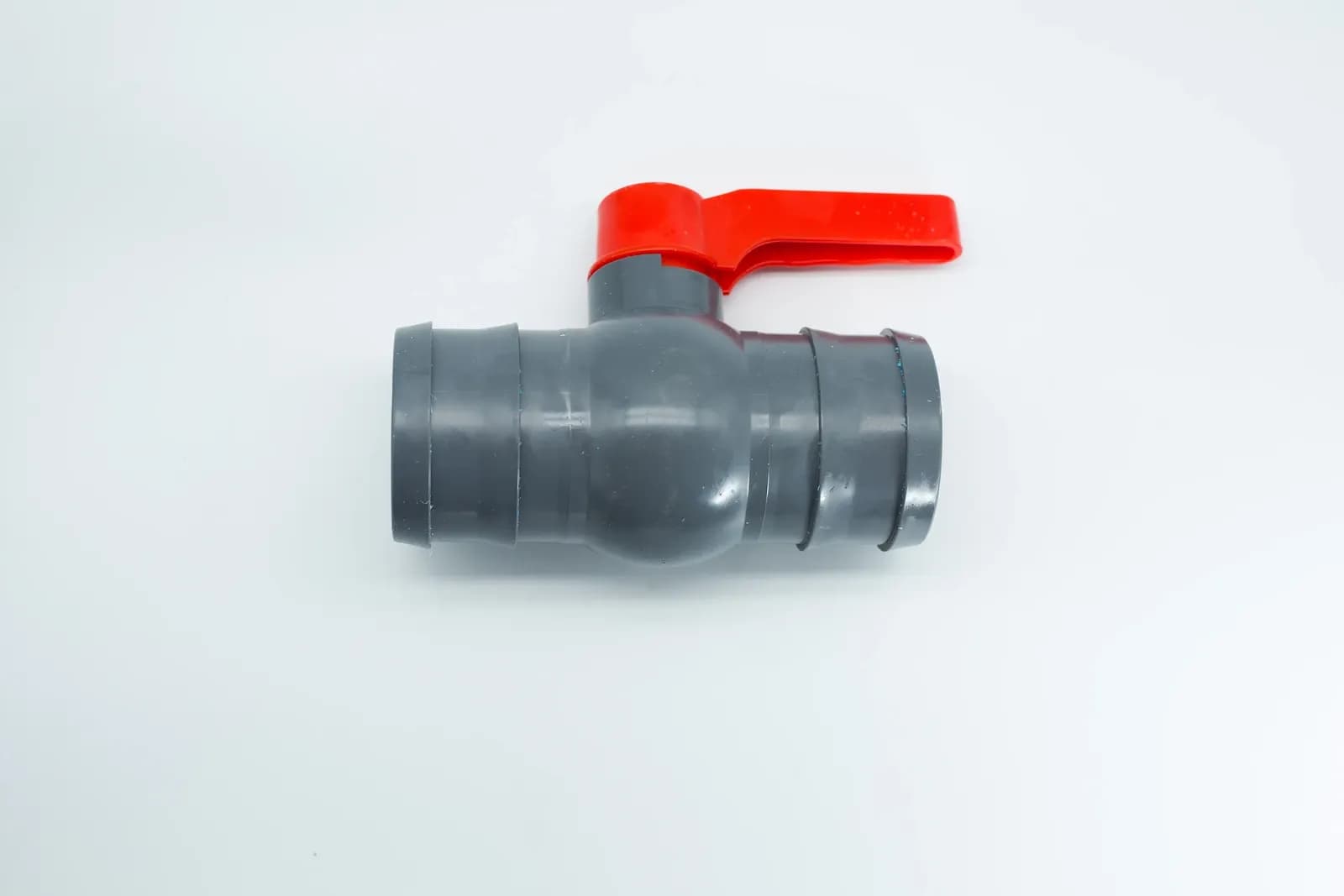
Manual irrigation valve body and ribbed hose connections from the IrriNex equipment collection. The photograph does not establish an approved motorized conversion. Photo: IrriNex.
The practical deliverable is a valve-by-valve reuse register and a staged acceptance plan. This guide includes an original fictional inventory to show how the decisions fit together. It does not establish compatibility for an unidentified valve, solenoid, decoder or actuator.
1. Record the existing installation before selecting replacements
Give each field valve a permanent identifier and mark the block it serves. Record the valve body, actuator or pilot assembly, existing control method, direction of flow and accessible identification. Photograph the actual assembly and its connections so that the supplier reviews what is installed, rather than a similar-looking catalog image.
Record its present job as well as its size. A valve used only for seasonal manual isolation has a different duty from one expected to switch several times every day. A pressure-regulating assembly also has a function to preserve beyond simply opening and closing.
Establish a working baseline while the existing system operates under an approved procedure. Note the active block, upstream and downstream pressure, available flow evidence, leakage, manual response and known faults. Identify what was measured, what came from documentation and what remains unknown.
Oregon State University Extension's April 2026 irrigation inspection guide treats the pump, electrical components, pipelines and distribution equipment as parts of one inspection. That whole-system view matters in a retrofit: an automation change should not conceal leaking pipework or an existing valve that cannot reliably stop flow.
Include shared equipment in the survey. Pumps, master valves, filtration and fertilizer injection may depend on the same operating sequence. Mark which person currently coordinates them, because a manual action performed reliably by that person may need an explicit control or interlock in the new arrangement.
2. Put each valve into a documented reuse category
Use four categories: retain the complete assembly, retain the body with an approved conversion, replace the assembly, or hold the decision pending evidence. The category describes the proposed action; it is not a substitute for checking the installed equipment.
| Category | When to consider it | Evidence needed before proceeding |
|---|---|---|
| Retain complete assembly | The existing actuation is suitable for the proposed control system | Identity, condition, electrical or hydraulic compatibility and functional checks |
| Retain body with approved conversion | The manufacturer supports a specific actuation or pilot change | Exact conversion parts, installation procedure and resulting operating limits |
| Replace assembly | Condition, duty or supported conversion does not meet the requirement | Replacement selection against actual flow, pressure, connections and control duty |
| Hold pending evidence | A material identification or compatibility question remains unresolved | Named question, responsible reviewer and a decision before automatic operation |
The FAO Handbook on Pressurized Irrigation Techniques, chapter 3, describes a common solenoid arrangement in which hydraulic pressure moves the main diaphragm or piston while a solenoid controls the pilot action. This explains why an electrical attachment and the hydraulic valve must be considered together. The handbook's example ratings and controller types are not universal specifications for a retrofit.
A solenoid that physically screws into an opening is not automatically an approved conversion. Pilot passages, seals, permitted pressure differential, actuation behavior and the complete assembly matter. Obtain the exact parts and support statement for the identified valve instead of treating thread fit as qualification.
For an ordinary manual rotary valve, adding a small pilot solenoid does not inherently create a powered operating mechanism. A suitable motorized conversion may require a supported mounting and drive arrangement, or the valve may need replacement. Keep that decision tied to the actual assembly and required service.
3. Match the retained actuation to the new control output
Record what each actuator actually requires. AC operation, continuously powered DC operation and pulsed latching operation are different interfaces. A familiar nominal voltage, wire color or connector shape is insufficient to establish compatibility.
The controller architecture guide provides the background distinctions. For the retrofit, ask the supplier to identify the supported controller output, solenoid or actuator reference, required signal and permitted loading for each retained assembly.
A decoder system adds another interface to check: the controller must support the decoder, and the decoder must support the connected actuator. Do not assume that an existing conventional station pair can simply be connected to a two-wire path or that matching nominal voltage makes devices interchangeable.
For existing field wiring, establish its route, conductor identity, condition and connection arrangement. The station and common-wire test map helps organize that evidence. Reuse should depend on the required checks for the new circuit, rather than the fact that a cable previously operated something.
Have electrical work performed through the appropriate qualified installer and equipment procedures. Disconnect relevant power before servicing, prevent unexpected remote starts and do not apply unsuitable test voltages to connected electronics. Similarly, isolate and relieve hydraulic pressure through the approved procedure before disturbing a valve or pilot connection.
4. Preserve hydraulic behavior when changing the control method
A retained valve body does not guarantee unchanged operating behavior after its pilot or actuator changes. Confirm the resulting opening and closing action, required differential pressure, flow direction and any effect on an existing regulating function. A conversion that opens in one demonstration may still fail at another intended operating condition.
Identify the conditions that matter for the farm: the lowest available supply pressure, smallest active block, highest expected demand and relevant downstream pressure. Request confirmation of the complete assembly's operating limits at those conditions. Do not substitute a maximum pressure rating for a minimum operating-differential requirement.
Check the physical installation as well. New adapters, fittings or an altered valve arrangement may change pressure loss and service access. Use the drip irrigation pressure-budget guide to review the changed hydraulic path. Automation cannot supply pressure that the system does not have.
Preserve the intended sequence between valves and the water source. The pump and valve interlock guide explains why a transmitted open command is not enough evidence to permit every dependent operation. Pump motors require their appropriate control equipment; a valve output should not be treated as a motor-power connection.
Record what happens when local manual control is selected, communication is lost or power returns. Confirm these behaviors for the converted configuration. A label describing the original valve does not establish the final behavior of a changed actuator, pilot circuit and controller together.
5. Use a mixed inventory to define the actual project scope
Consider a fictional survey of nine block valves. The following findings are assumed for illustration, including the availability of manufacturer support. They are not judgments about unidentified equipment or claims that any particular percentage of farm valves can be reused.
| Field identifiers | Survey finding | Proposed action | Remaining acceptance requirement |
|---|---|---|---|
| A1–A4: four valves | Existing identified AC assemblies are supported by the proposed outputs | Retain complete assemblies | Verify wiring condition and installed operation |
| B1–B3: three valves | Identified hydraulic bodies have documented supported conversion kits | Retain bodies and fit the specified conversions | Verify the resulting pilot and control behavior |
| C1: one valve | The inspected manual assembly is damaged and unsuitable for the intended duty | Replace with a selected complete assembly | Confirm hydraulic, connection and control compatibility |
| D1: one valve | Identity and supported operating limits remain unconfirmed | Hold the automation decision | Resolve the evidence gap and approve a defined action |
The inventory reconciles to four + three + one + one = nine valves. Seven existing bodies are candidates for retention, but only four complete assemblies are candidates for unchanged reuse. Those are different claims. Conversion parts and labor remain in the scope for B1–B3, and none of the categories removes the need for installed acceptance.
Eight valves have a defined proposed automation action, while D1 remains unresolved. Do not advertise the nine-block project as complete because eight lines have a purchasing decision. Determine how D1 will be managed and whether its unresolved state affects shared pump operation or the promised automated sequence.
Turn the register into a quotation with separate rows for retained equipment inspection, conversion parts, replacement equipment, field wiring, control interfaces, installation, commissioning and documentation. A count of retained bodies alone cannot establish project savings or the remaining service life.
6. Prove one representative conversion before expanding
Select a trial block that represents a real conversion requirement and can be supervised without compromising crop irrigation. Agree the operating window, acceptance conditions and restoration plan with the farm operator and installer. Keep the previous configuration record and the parts needed for an approved restoration arrangement where applicable.
Test the proposed configuration as a whole: controller output, field connection, actuator or pilot, valve and dependent equipment. Record the exact parts and settings used. A successful test with a different solenoid or temporary power supply does not validate the final proposed combination.
| Stage | Evidence to retain | Decision before moving on |
|---|---|---|
| Existing baseline | Equipment identities, known faults and operating observations | Is the original condition understood? |
| Compatibility review | Approved component combination and applicable limits | Does the proposed change have sufficient support? |
| Supervised trial | Installed starts, stops, indications and relevant hydraulic observations | Did this configuration meet its agreed acceptance conditions? |
| Shared-system review | Pump, filtration, injection and local-control interactions | Can the converted block operate within the complete sequence? |
| Next-stage release | Updated register, unresolved items and restoration instructions | Which additional valves are actually covered by the evidence? |
Compare trial results with the baseline under comparable conditions. A change in block demand or water-source pressure can affect the comparison, so record those conditions rather than attributing every difference to the conversion. Define acceptance with the responsible designer; a small numerical difference alone does not prove a pass.
If the trial exposes a fault, restore an approved operating arrangement or keep the block under a specifically agreed supervised procedure. Do not repeatedly force the actuator or bypass pump protections to finish the demonstration. Update the parts or design decision before repeating the affected check.
7. Hand over the changed system, including retained equipment
For each completed valve, record what remained, what changed and the accepted final configuration. Include current component references, pilot arrangement where applicable, wiring or decoder identity, field label, operating limits and approved local procedures.
Attach the trial evidence to the equipment it actually covers. A conversion proved on B1 does not automatically qualify a different body version, another pilot arrangement or a block with materially different pressure conditions. State what can be carried forward and what needs additional verification.
Train the operator on manual mode, visible indications, scheduled behavior and the response to unresolved faults. Keep installation records and essential operating instructions available at the farm. Retained equipment still needs inspection and spare-part planning after it becomes part of a new automatic system.
Close the project against the reuse register. Every valve should have an accepted final action or a clearly documented remaining limitation, and the delivered scope should match the claim made to the farm. That record makes selective reuse defensible and later maintenance practical.
8. Frequently asked questions
Can every hydraulic irrigation valve be converted with a solenoid?
No universal conversion should be assumed. Identify the body and pilot arrangement, obtain the manufacturer's supported parts and limits, and verify the resulting assembly in its intended installation.
Can I keep existing valve wiring when changing controllers?
Possibly, if its identity, condition and electrical characteristics meet the proposed system's requirements. Confirm the circuit architecture and required checks; previous operation or a matching wire count does not establish compatibility.
Does retaining the valve body guarantee a cheaper retrofit?
No. Compare inspection, conversion parts, wiring, installation, commissioning and maintenance alongside replacement costs. Reuse is valuable when the complete supported arrangement meets the required duty and provides a suitable operating life.