Hydraulic Pilot Tubing for Irrigation Valves: Routing and Fault Diagnosis
Hydraulic pilot tubing on an irrigation control valve must connect the correct pressure source, control chamber, pilot and return or drain points exactly as the approved circuit specifies. Label both ends, record the tube dimensions and installed route, and compare pressure observations in the correct operating state before diagnosing a blockage. Tubing that looks tidy can still connect the wrong ports.
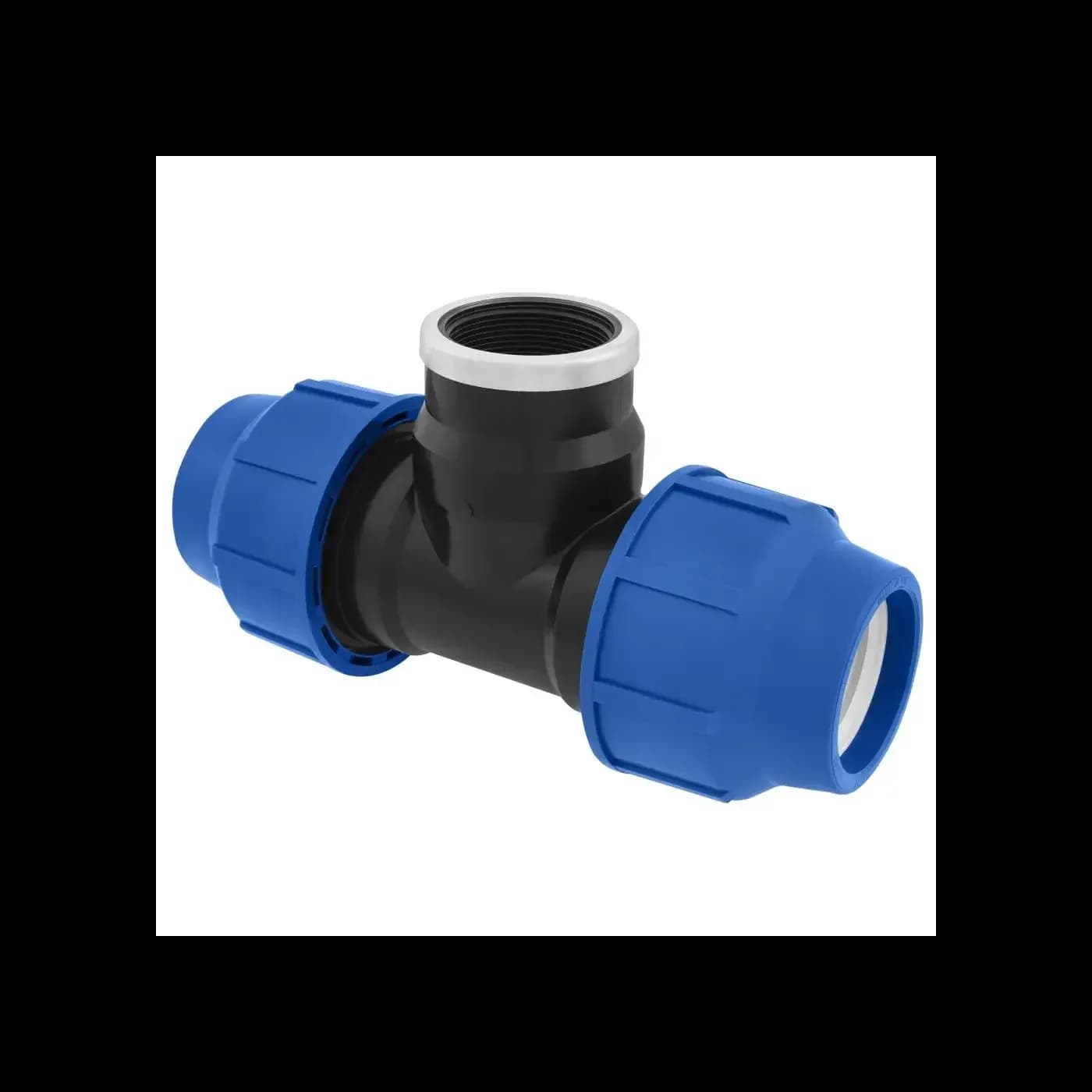
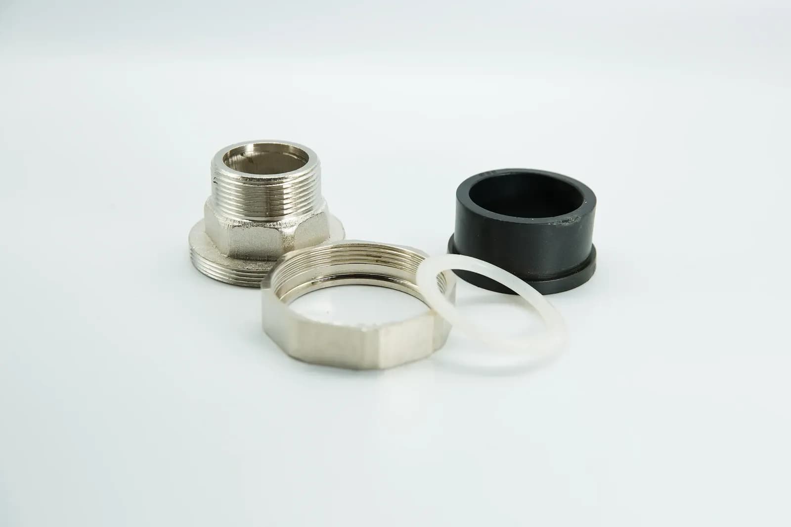
Threaded connection body, nut, black sleeve and white ring from the IrriNex equipment collection. The photograph illustrates component identification; it does not establish suitability for a hydraulic pilot circuit. Photo: IrriNex.
This guide builds a pilot-line register and a diagnostic record. Its original calculations explain why internal bore, length and elevation matter. They are hypothetical examples, not an authorization to resize tubing, alter a restrictor or reconfigure a valve.
1. Trace the actual circuit before touching the tubes
UF/IFAS guidance on irrigation valves explains that a hydraulic control signal can be transmitted through small tubing to the actuator. The operating result depends on pressure differences and the fitted valve arrangement. Do not assume that every irrigation diaphragm valve has the same normally open or normally closed behavior.
Obtain the connection diagram for the exact valve, pilot, solenoid and control accessories. Record the model identities and drawing revision. A pressure-reducing assembly, pressure-sustaining assembly and simple on/off valve can share a similar main body while using different pilot connections.
Identify the actual upstream and downstream mainline directions. Trace any separate pilot supply, pressure-sensing connection, strainer, restrictor, check device, manual selector and drain. A small tube can carry operating water, transmit a sensing pressure, or perform more than one role during different states.
Use the diaphragm and pilot operation guide for the general mechanism. The field record must go further by assigning every visible tube to the supplied circuit. Similar colors or adjacent ports do not establish that assignment.
2. Give both ends the same traceable line identity
Choose a durable line identifier and apply it at both ends without obstructing service or damaging the tubing. Retain the original component port markings alongside the new field identifier. An equipment label such as C may mean something specific in that manufacturer's diagram; this worksheet must not redefine it by guesswork.
| Field role label | Endpoints to record from the approved diagram | Additional information |
|---|---|---|
| L-S: supply route | Verified pressure source and its assigned receiving port | Included strainer, restrictions and available supply conditions |
| L-C: chamber route | Control node and the designated chamber interface | Exact chamber connection and functions in each state |
| L-D: return or drain route | Designated pilot outlet and documented destination | Return pressure, outlet condition and whether water crosses the main meter boundary |
| L-P: sensing route, where fitted | Defined pressure-sensing point and designated pilot sensing port | Tap elevation, isolation state and whether the circuit carries continuous flow |
These role labels are examples for a register, not a universal circuit or port-connection instruction. A supplied assembly may combine roles, add lines or omit one entirely. For each actual line, add internal diameter, outside diameter, material specification, length, fittings and the reference photograph.
Photograph the connection before removal, with its tag and component marking legible. If an undocumented assembly has already been disconnected, stop using color or tube length as a reconstruction method. Resolve the exact connection arrangement from the supplier's diagram and the installed components.
3. Route for access while preserving the specified tubing
Keep the approved tube size and material through a replacement. Matching only outside diameter can leave a different internal bore. Matching the bore can still leave an incompatible wall thickness, fitting grip or pressure and temperature capability. Retain the fitting and tubing compatibility evidence together.
Route lines clear of sharp edges, hot surfaces, moving linkages and places where a service lid or tool can pinch them. Observe the tubing manufacturer's bend-radius and support requirements. Provide the documented service movement without leaving a long unsupported loop that can snag. No universal bend radius or support spacing is assigned here.
A restrictor or needle setting is part of the control circuit. Do not enlarge an opening, remove it or substitute a larger tube because a valve appears slow. Such changes can alter chamber flow and the main valve's response. Record the existing setting before approved adjustment, and keep the intended sequence and pressure limits in the review.
Where a pilot depends on a protected water supply, identify the actual strainer and its service procedure. The irrigation water and filtration specification guide helps frame contamination evidence. A laboratory result does not identify which particular pilot opening is obstructed.
4. Understand bore sensitivity during flowing conditions
The OpenStax treatment of laminar tube resistance relates pressure loss to viscosity, tube length, flow and the fourth power of internal radius. Written using internal diameter D, the steady fully developed laminar-flow relation is ΔP = 128μLQ/(πD⁴). Here μ is dynamic viscosity, L is length and Q is volume flow.
For an original comparison, assume a straight horizontal circular tube carrying clean, incompressible Newtonian liquid. Use constant viscosity 0.001 Pa·s, density 1,000 kg/m³ and an imposed flow of 20 mL/min, equal to 0.0000003333 m³/s. Assume laminar fully developed flow and ignore entrance, fitting and localized restriction losses. These are calculation inputs, not an approved pilot-water specification.
| Case | Length | Internal diameter | Calculated tube friction loss | Tube liquid volume |
|---|---|---|---|---|
| A | 3 m | 2 mm | 2.55 kPa | 9.42 mL |
| B | 3 m | 1 mm | 40.74 kPa | 2.36 mL |
| C | 6 m | 2 mm | 5.09 kPa | 18.85 mL |
Halving the bore from case A to B raises the calculated resistance by 16 times. Doubling length from A to C doubles it. At the stated flow, mean velocities are approximately 0.106 m/s in the 2 mm tube and 0.424 m/s in the 1 mm tube. The corresponding Reynolds numbers, calculated as density × velocity × diameter / viscosity, are about 212 and 424, consistent with the assumed laminar regime.
A real circuit may supply a limited pressure difference rather than hold this imposed flow. In that case, adding resistance changes flow; the table does not predict that the original 20 mL/min persists. A kink, partially blocked fitting or damaged bore is not a uniform circular tube, so this formula cannot quantify that defect simply by assigning an apparent diameter.
Tube volume is calculated from πD²L/4. Dividing case A's volume by the example flow gives about 28.27 seconds to replace one tube volume under the stated steady-flow assumption. This is not a pressure-signal travel time or a main-valve opening time. Chamber movement, compliance, trapped gas, pilot action and the rest of the circuit determine dynamic response.
5. Separate elevation effects from friction and trapped pressure
Friction loss in the previous equation requires flow. A connected, liquid-filled sensing line with no steady flow has no steady friction loss from that equation, but elevation still changes its hydrostatic pressure. A restricted line can also retain an old pressure when its connection to the source is blocked, so apparently stable readings do not establish that it is responding correctly.
For a separate hypothetical static example, put a pressure tap 1.50 m below the pilot sensing point. Assume a continuous water column, density 1,000 kg/m³, gravitational acceleration 9.81 m/s² and no flow. Pressure at the higher point is lower by 1,000 × 9.81 × 1.50 / 1,000 = 14.715 kPa. A lower-tap reading of 300 kPa gauge corresponds to approximately 285.285 kPa gauge at the higher point on the same atmospheric reference.
That difference is not evidence of tube friction or a clogged restrictor. Conversely, subtracting the elevation effect does not prove a line is clear during a changing command. Record measurement locations, reference basis, times and operating state. Check the response using the model's approved procedure.
A pilot drain connected to a pressurized return experiences a different boundary from an atmospheric outlet. Do not move the drain to a convenient destination without checking the supplied circuit. The pressure-regulating valve operating-range guide helps relate pilot behavior to the main valve's actual duty.
6. Diagnose the route, not just the visible symptom
Begin with a safe external inspection and the line register. Compare the installed connections with the correct diagram before changing a setting. Record whether the symptom occurs during opening, closing, stable regulation or after maintenance. Several faults can produce similar main-valve behavior.
| Observation | Next evidence to obtain | What cannot yet be concluded |
|---|---|---|
| Valve behavior changed after tubes were replaced | Both-end identities, actual port map, bore, fittings and restored settings | The main diaphragm failed |
| Pressure does not follow an approved command change | Defined source, chamber and return observations; sensor response; available pilot path | One visible tube must be blocked |
| Regulation varies when another branch operates | Current upstream supply, sensing location and return pressure under that combination | The pilot adjustment alone is incorrect |
| Persistent leakage at a tube connection | Specified tube/fitting match and condition after verified isolation | Further tightening is the correct repair |
Use only the specified test ports and suitable instruments. Do not loosen a live tube to see whether it sprays, and do not force wire through a calibrated orifice. Before dismantling, isolate every relevant supply and verify depressurization according to the equipment procedure. A separate pilot feed can remain pressurized after the mainline is isolated.
The electrical-versus-hydraulic troubleshooting guide provides the wider fault sequence. Keep this pilot record focused on connection identity, pressure boundaries and the observed response, rather than replacing every possible component at once.
7. Recommission the documented configuration
After an approved repair, verify line identities, tube specifications, fittings, service isolations and recorded settings. Remove temporary test arrangements only through the specified procedure and restore the intended supply and return paths. Update the drawing if an authorized configuration change was made.
Run the permitted water-only operating checks for opening, closing and regulation as applicable. Record the command, relevant mainline pressures, pilot observations, response and final condition. A successful local manual action does not by itself verify the remote pilot route, so exercise the required control modes separately.
Retain the fault evidence and the exact change with the resulting observations. If response remains outside the project criteria, return to the circuit assessment. A neater route or a newly replaced tube is not the acceptance result; the documented function of the installed configuration is.
8. Frequently asked questions
Can pilot tubing be replaced with any tube of the same outside diameter?
No. Confirm internal bore, material, wall, pressure and temperature capability, fitting compatibility and the supplied circuit requirements. The same outside dimension does not establish the same hydraulic or mechanical behavior.
Does a long pilot tube always lose pressure?
A flowing tube can have friction loss. A static liquid-filled sensing line requires a separate elevation check, while a blocked or gas-affected line may give misleading or delayed observations. Identify the state before interpreting the readings.
Should I remove a restrictor to make a valve respond faster?
Only carry out a configuration change specifically approved for the actual assembly. The restrictor can affect chamber flow and valve dynamics. Diagnose the path and verify the intended response before changing it.