Technical2026-10-15
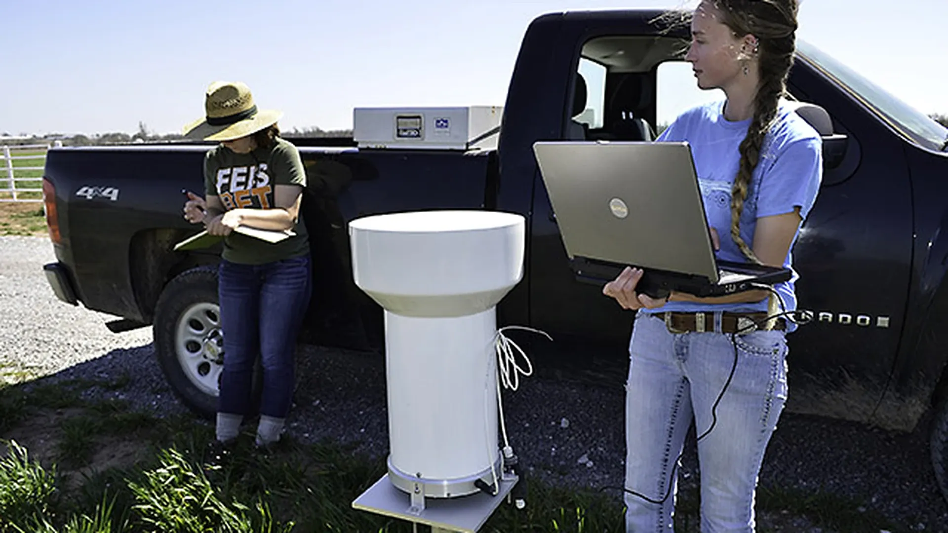
Good farm rain gauge placement keeps the collector level, clear of IrriNex sprinkler series spray and splash, and far enough from trees, buildings and other obstructions to reduce wind and rain-shadow errors. Treat the gauge as an irrigation water management instrument: document its exposure, inspect it after storms, and compare questionable totals with nearby independent evidence before changing an irrigation schedule.
Technicians read a recording rain gauge at the USDA Agricultural Research Service Grazinglands Research Laboratory in Oklahoma. The real agricultural monitoring equipment shows field context; it does not certify any placement distance in this guide. Photo: Ann Marshall / USDA ARS. Cropped, resized and encoded as WebP.
A rain gauge measures precipitation at one point. It does not directly measure how much water entered every root zone, and a badly exposed gauge can create a consistent bias that software cannot repair. This guide provides a site-selection scorecard, a commissioning test, an inspection log and rules for deciding when a reading is usable, questionable or invalid.
Write down what the gauge will control. It may document storm depth, trigger a controller rain delay, support a daily soil-water balance, or help estimate effective rainfall. The decision sets the required response time, maintenance access and acceptable uncertainty. A manual gauge read once each morning can support records; a tipping-bucket sensor connected to automation also needs power, communications, event timing and a safe failure state.
Do not confuse measured rainfall with effective rainfall. Leaves intercept water, runoff removes it, and deep drainage can carry it below the active root zone. After obtaining a defensible gauge total, use the effective rainfall guide for irrigation to decide how much can reduce the next application. Keep the raw precipitation value unchanged and calculate agronomic adjustments in separate fields.
Name the field or management zone represented by the gauge. Record coordinates, elevation, crop, surrounding cover, irrigation method and intended controller or report. On a large farm, one convenient gauge beside the office may not represent storms, elevation or wind exposure at distant blocks. Add gauges only when each has a defined zone and an owner; more unattended instruments do not create better evidence.
Walk the site before installing hardware. Look in every direction from the height of the collector rim. Trees, windbreaks, buildings, tanks, grain bins and tall crops can deflect wind and block precipitation. A low object close to the gauge can matter more than a taller object far away. Measure the obstruction height above the gauge rim and its horizontal distance; do not estimate both from a map.
The linked National Weather Service rain-gauge setup guidance advises avoiding large obstacles and illustrates a practical two-times-height separation. It also calls for a level gauge, protection from strong wind where possible, no sprinkler influence and no surface that can splash into the collector. Apply the governing network or manufacturer rule if it is more specific; record the rule used rather than presenting one ratio as universal.
| Potential influence | Field check | Preferred action |
|---|---|---|
| Tree or shelterbelt | Measure height above rim and distance; note prevailing storm winds and future growth | Move beyond the applicable separation rule and schedule a seasonal vegetation review |
| Building, bin or tank | Check roof runoff, turbulence, wall eddies and reflected splash | Select open ground with a stable, accessible mount rather than a roof or wall edge |
| Tall crop | Estimate mature canopy height, not seedling height at installation | Allow for growth or use a documented seasonal relocation procedure |
| Uneven terrain | Identify ridges, hollows and channels that accelerate or shelter wind | Choose exposure representative of the managed field, avoiding extreme local airflow |
Photograph the horizon from the gauge position in four directions. Repeat the photographs after construction, tree growth or a crop-height change. A location can pass at commissioning and become biased later. Keep the original site drawing so a relocation does not silently break the time series.
A farm gauge must measure natural precipitation when it is used to adjust irrigation. Place it outside the wetted pattern of pivots, travelers, solid-set sprinklers, end guns and yard sprinklers. Consider wind drift, not only the dry-weather nozzle radius. Observe at least one representative irrigation cycle under normal pressure and wind before approving the location.
Keep the collector away from roofs, concrete, plastic mulch, metal covers, equipment decks and bare surfaces that can rebound drops into the opening. The rim must also be high enough to reduce soil splash and low vegetation interference under the applicable method. Do not raise it onto a roof to solve splash; stronger wind and turbulence can create another, often larger, error.
If the same device must measure sprinkler application uniformity, label that as a separate catch-can test. Temporary collectors inside a wetted pattern answer a different question from the permanent rain gauge used for weather data. Store the two datasets under different sensor IDs so irrigation water is not mistaken for rainfall.
Wind accelerates around sharp edges and over elevated sites. Airflow can carry droplets over the opening, causing undercatch even when nothing visibly blocks the sky. The best farm site is usually open enough to avoid rain shadow while receiving reasonably uniform shelter in all directions. A narrow gap between buildings, a hill crest and the top of a shed are poor compromises.
Record prevailing storm directions and any persistent crosswind. If the site is unavoidably windy, consult the gauge instructions or the responsible monitoring network about an approved wind shield. Do not build an improvised shield that becomes a splash surface or changes the collector geometry. A shield is part of the measurement configuration and must be logged, inspected and kept level.
When two candidate sites differ, run both gauges through several storms before committing automation to either. Compare event totals, timing, wind and nearby independent observations. Consistent divergence during windy storms is more informative than agreement during one calm shower. Do not average two biased exposures and call the result correct.
Follow the exact manual for the collector. The opening must be horizontal, the body vertical where required, and the mount stiff enough that wind or service work cannot change the angle. Use corrosion-resistant fasteners and a foundation suited to saturated soil, frost and machinery vibration. Protect cables from livestock, rodents, tillage and UV exposure without creating a new runoff path into the collector.
Make routine access possible without walking through a crop bed or parking equipment beside the gauge. Technicians should be able to clean the funnel, check the level and download data without touching the collector rim. If the mounting post is also used for a solar panel, antenna or enclosure, ensure those parts cannot drip, shade or splash into the gauge.
A clean, level collector can still produce wrong records if its pulse factor, time zone or channel mapping is wrong. Record the gauge type, serial number, orifice dimensions, resolution, pulse depth, logger channel, sampling interval, reporting unit and time base. Preserve raw tips or raw depth before any software correction.
For a tipping bucket, perform only the verification method specified by its manufacturer or monitoring program. A fast pour can overwhelm the mechanism and is not equivalent to rainfall. Use the specified water volume and delivery rate, record observed tips, and calculate the difference without changing an adjustment screw unless an authorized procedure requires it. Confirm that one physical input produces one correctly timed record in the destination platform.
If pulse data feed an irrigation controller or dashboard, use the pulse conversion guide to document scaling and rollover logic. Rain-gauge pulses represent depth per tip, while flow-meter pulses often represent volume; keep their units and channels separate.
| Item | Record | Acceptance evidence |
|---|---|---|
| Exposure | Coordinates, rim height, four-direction photos, obstruction measurements | Site meets the chosen siting rule and excludes sprinkler spray and splash |
| Mount | Level readings, fasteners, foundation and access route | Collector is level, rigid and serviceable |
| Sensor | Identity, resolution, configuration and approved verification result | Input is detected within the applicable procedure |
| Data chain | Channel, unit, pulse factor, timestamps and destination field | Raw event and displayed total reconcile without unexplained conversion |
| Control action | Zone, delay or water-balance rule, owner and safe fallback | A test record produces the expected review or action, with no hidden automatic change |
Review the event shape, not only the daily total. A flat zero during a confirmed storm can indicate blockage, communication loss or a wrong time window. An isolated tip on a clear day can come from vibration, condensation, maintenance or irrigation splash. A sudden step exactly when a pivot passes the site is not credible natural rainfall without other evidence.
Compare questionable data with nearby gauges, radar, field observations and soil-moisture response. These are corroborating sources, not automatic replacements. Radar estimates cover an area and have their own bias; another gauge may be kilometres away; soil response depends on infiltration and sensor position. Keep the original reading and append a quality flag, reason and reviewer.
Use the soil-moisture sensor placement guide to interpret whether wetting at monitored depths is plausible. A rain gauge can confirm water reached its opening, while a soil sensor can help show whether water entered one monitored soil volume. Neither alone proves uniform root-zone recharge.
| Flag | Use in irrigation calculation | Required follow-up |
|---|---|---|
| Accepted | Use the raw depth, then calculate effective rainfall separately | Routine inspection and record retention |
| Questionable | Hold automatic schedule reduction until review | Compare independent evidence and inspect exposure, funnel and logger |
| Invalid | Exclude under a documented rule; never replace silently | Record reason, source of any substitute value and authorization |
| Missing | Apply the farm's conservative fallback | Restore the data path and document the outage window |
Leaves, insects, bird material, dust and algae can partly block the funnel before they stop it completely. Inspect after severe wind, dust, hail and harvest activity, and at a routine interval appropriate to the site. Empty manual gauges at the defined observation time. For electronic gauges, check the funnel, screen, bucket movement, level, cable, power and communications without erasing raw records.
Link maintenance events to data-quality flags. If a funnel was found blocked on Monday, the uncertainty begins after the last confirmed clean inspection, not only at the discovery time. Never reconstruct missing rain from the next accumulated total unless the sensor design and a documented method support that interpretation.
Define how the gauge changes operations. A simple rain delay may pause starts after a threshold; a soil-water balance may subtract a reviewed effective-rainfall estimate; an advisory system may only notify an operator. Write the persistence, time window, affected zones, maximum delay and reset rule. The evapotranspiration and field water-budget guide helps separate a temporary weather response from a broad runtime change.
Set a conservative response for missing or questionable data. Automation should not assume a zero because the gauge stopped communicating, and it should not cancel a critical irrigation from one implausibly high tip count. Use the remote irrigation alarm design guide to give each alert an owner, context and action.
Retain the raw depth, quality flag, effective-rainfall calculation, schedule change and operator approval as separate fields. This creates an audit trail and lets the farm revise agronomic assumptions without rewriting sensor history. When software maps multiple gauges, check that each field points to the intended sensor and unit.
A placement worksheet should include the decision served, candidate locations, obstruction measurements, sprinkler exclusion, splash surfaces, wind notes, mature vegetation height, access, communications and safety. Score each candidate against the same rules. Record why the final location was selected and which compromise remains.
Review the site at least when crops reach mature height, trees leaf out, irrigation equipment changes, a building is added, or the gauge is struck or relocated. Create a new configuration record after relocation; do not splice the coordinates and exposure into the old record. If continuity matters, overlap old and new gauges through several events and label the comparison period.
The operational result is a traceable chain: suitable exposure, level installation, verified data mapping, inspected hardware, quality-controlled storm depth and a separate effective-rainfall decision. That chain makes the rain gauge useful for irrigation water management without pretending one point measurement represents an entire farm.
Use the rule required by the gauge manufacturer or monitoring program. A widely used practical guide places the gauge at least twice as far from an obstruction as the obstruction is tall, measured relative to the gauge, but other standards can differ. Record height, distance and the adopted rule.
Only if its weather-measurement location remains outside all sprinkler water and wind drift, or if it is clearly designated as a temporary application collector. A permanent weather gauge receiving irrigation water cannot reliably separate natural rainfall from applied water.
Usually no. Roof edges and elevated sites expose the collector to accelerated wind, turbulence and runoff. Choose a stable ground-level site with proper clearance and rim height under the applicable guidance.
Only when its exposure and local storms adequately represent all affected zones, which must be demonstrated rather than assumed. Large, topographically varied or storm-prone farms may need multiple defined gauges, with mapping, maintenance and data-quality rules for each.
The distance between the rain gauge and any obstacle (trees, silos, buildings) must be at least twice the height of the obstacle ($D \ge 2H$). If a windbreak tree line is 10 meters tall, the rain gauge must be sited at least 20 meters away.
Wind causes significant 'undercatch': wind striking the cylindrical gauge body creates an upward air vortex over the funnel opening, blowing small raindrops right over the collector. At wind speeds of 20 km/h (12 mph), undercatch exceeds 15% to 25%.
It is a ring of freely hanging, vertical metal baffles surrounding the rain gauge at orifice height. The baffles deflect horizontal wind downward, creating a calm, non-turbulent air pocket directly over the funnel, reducing wind undercatch error to under 3%.
Tipping buckets rely on symmetrical gravitational balance between two calibrated plastic spoons (e.g. 0.2mm per tip). If the gauge is tilted by even 2 degrees off-level, one side tips early and the other side tips late, skewing rainfall intensity and total volume.
Products relevant to this irrigation guide.
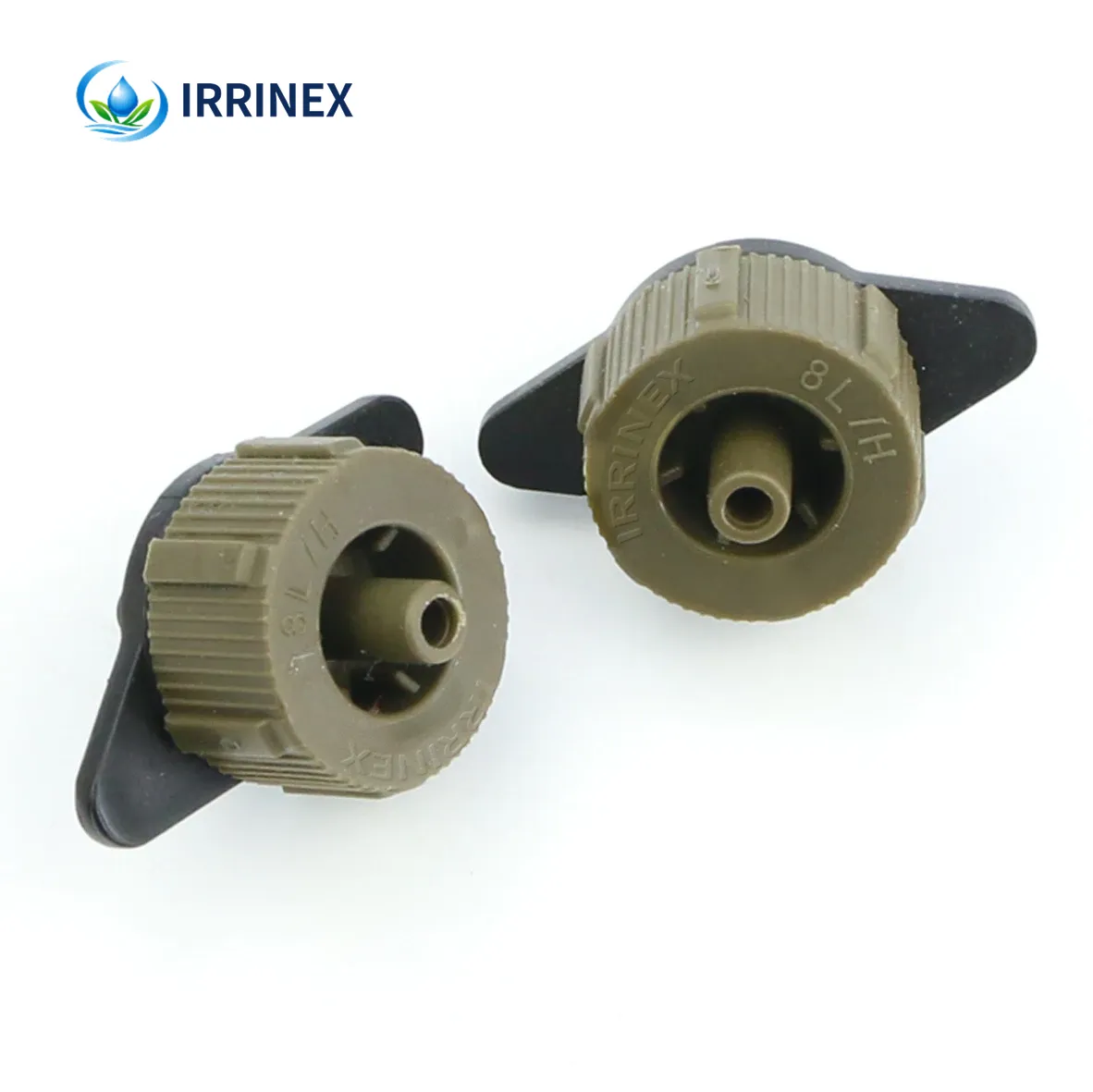
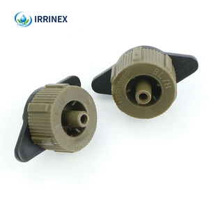
IRRINEX pressure-compensating dripper. Working pressure: 0.8-4Mpa; Size: DN6mm. A pressure-compensating dripper provides a selected drip outlet in an irrigation line. Compare the exact nominal flow and stated operating information without assuming a uniformity guarantee.
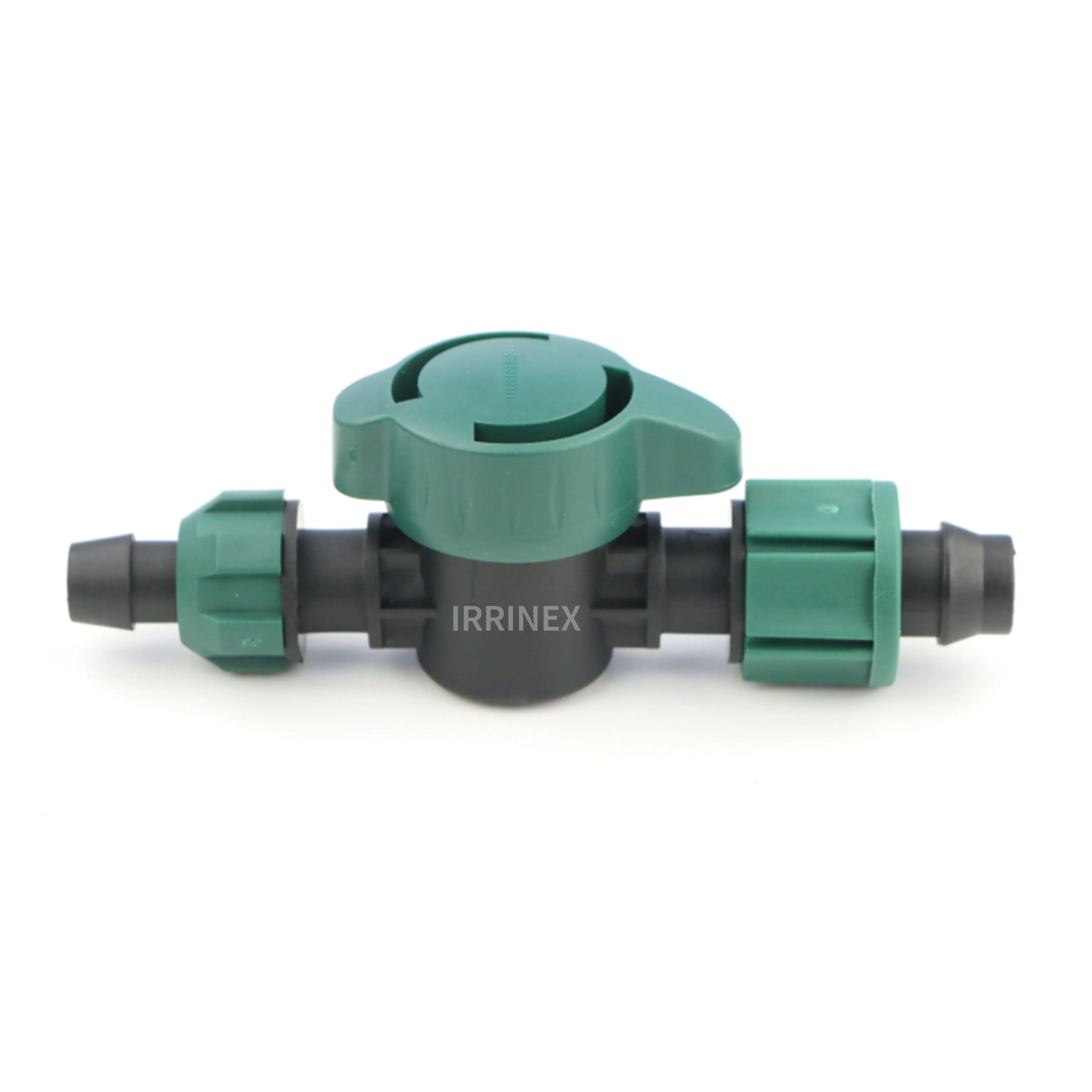
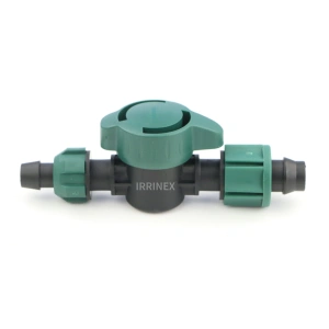
IRRINEX irrigation valve. size: Diameter 16mm. An irrigation valve forms part of the system's flow-control arrangement. The named valve form and its actual connections should be checked before choosing a configuration.
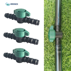
IRRINEX irrigation valve. Size: 16mm 20mm. An irrigation valve forms part of the system's flow-control arrangement. The named valve form and its actual connections should be checked before choosing a configuration.
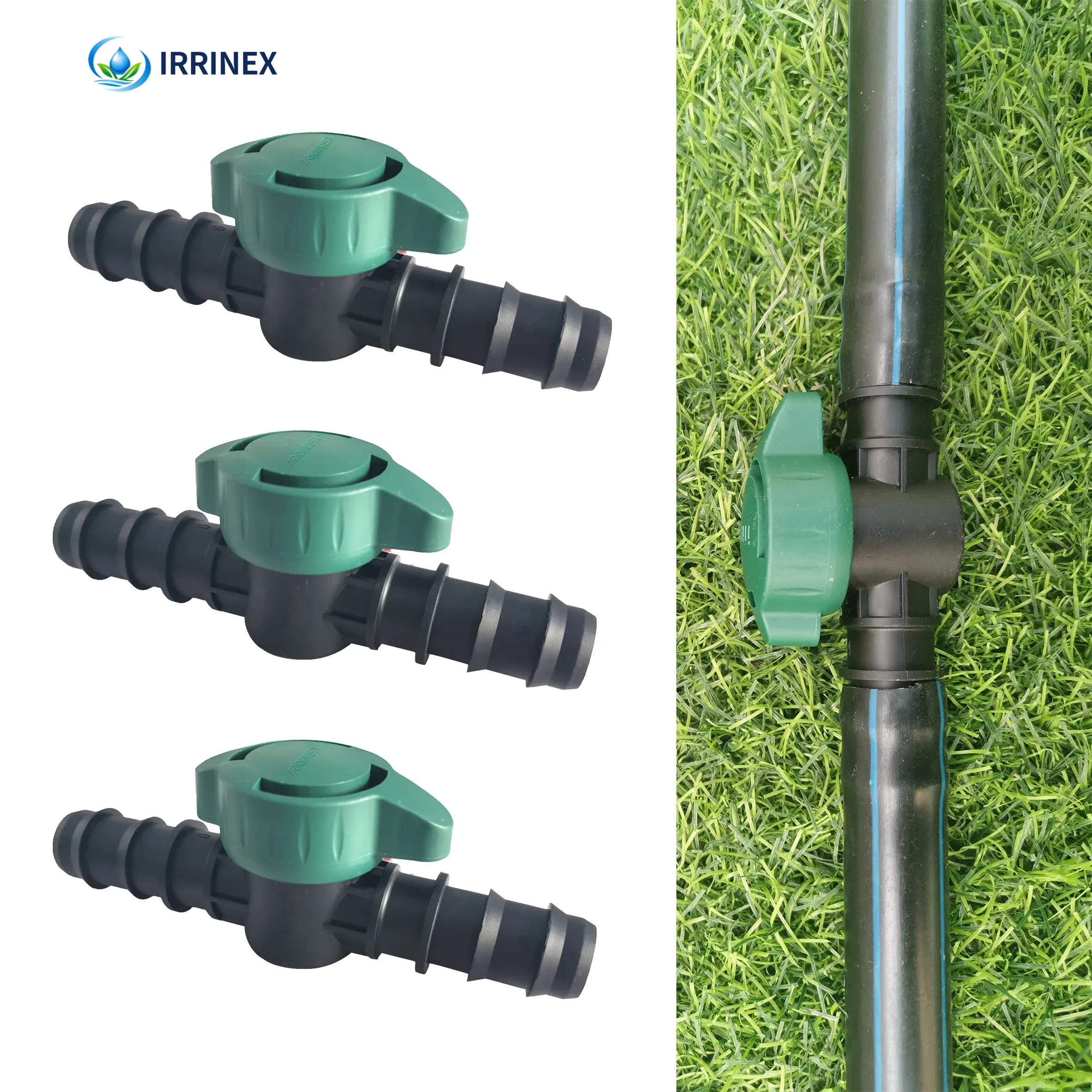
IRRINEX irrigation valve. Size: Diameter 16mm,20mm,25mm; Connection: +86 +86 17300766401. An irrigation valve forms part of the system's flow-control arrangement. The named valve form and its actual connections should be checked before choosing a configuration.