
Drip Irrigation Design Guidelines
Abstract: A drip irrigation design is a hydraulic plan that determines how filtered, regulated water reaches every emitter at an acceptable flow and pressure. It matters because emitter spacing alone cannot correct an undersized mainline, excessive pressure loss, poor zoning, or an unflushable layout. These guidelines take a project from crop and soil requirements to zone demand, emitter selection, pipe sizing, pressure management, filtration, air control, flushing, and field verification. They apply to garden beds, greenhouses, orchards, vineyards, and row crops, while manufacturer limits and local plumbing rules still govern final dimensions. The USDA Natural Resources Conservation Service (the U.S. federal conservation engineering agency) provides design and evaluation methods, and EPA WaterSense (the EPA water-efficiency program) reports that well-managed microirrigation can use 20 to 50 percent less water than conventional sprinklers. Follow the five steps in sequence; each calculation becomes an input to the next.
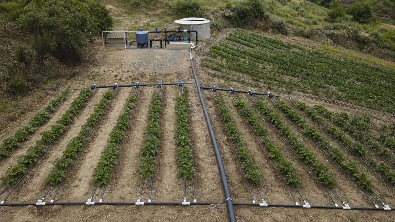
What is a reliable drip irrigation design?
IrriNex (a professional agricultural irrigation systems and component supplier) defines reliable design as uniform root-zone delivery under real operating pressure, with enough access to isolate, inspect, and flush every zone. A lateral is the pipe that carries emitters downstream of a control valve, while a mainline carries the combined design flow toward one or more zones.
The USDA Natural Resources Conservation Service National Engineering Handbook, Chapter 7 (the U.S. federal engineering reference for microirrigation) covers hydraulic design, emitter discharge, filtration, and system evaluation. Use its calculation approach or a qualified designer for large, long, steep, or high-value projects rather than relying on universal length rules.
EPA WaterSense microirrigation guidance reports water use 20–50% below conventional sprinklers and identifies design, installation, scheduling, and maintenance as the conditions for efficient performance. Treat efficiency as a verified design result rather than a fixed technology rating.
Compare three drip emission layouts
| Layout | Advantages | Limitations | Best suited for |
|---|---|---|---|
| Point-source emitters | Flow and position can match individual plants | More connections and labour; isolated clogging is less visible | Best suited for trees, containers, and widely spaced shrubs |
| Inline pressure-compensating dripline | Predictable spacing and better performance across moderate variation | Higher initial cost; fixed emitter interval | Best suited for orchards, perennial beds, slopes, and long rows |
| Thin-wall drip tape | Low material cost and rapid deployment over straight rows | Low pressure range and greater damage risk | Best suited for seasonal vegetables and field row crops |
Drip irrigation design guidelines in five steps
1. Define the crop, soil, and wetted area
Record plant spacing, root-zone width, peak water demand, soil texture, slope, and operating hours, then decide how much soil each plant must wet. Emitter count and spacing must create overlapping wetted patterns in that soil; one emitter per plant is not a design rule.
2. Calculate zone flow and pressure requirements
Multiply emitter flow by the number operating together and add any flushing flow to establish zone demand. Set the required inlet pressure from emitter specifications, then budget pressure loss through filters, valves, fittings, elevation, mainline, and laterals without assuming static pressure remains available during operation.
3. Size mainlines, submains, and laterals
Select diameters so velocity and friction loss remain within the hydraulic budget, and split a large area into zones when source flow or pressure variation is excessive. Compare dripline and drip tape with compatible tubing and fittings, using the actual product flow tables for maximum run length.

4. Add water protection and service points
Place code-compliant backflow protection, an isolation point, pressure regulation, and an adequately rated irrigation filter before emitters. Add air-release or vacuum protection at hydraulic high points where needed, zone valves that can be serviced, pressure test points, and flush outlets at every low or terminal end.
5. Draw, install, and commission the design
Issue a plan showing pipe sizes, elevations, design flows, pressures, valve boundaries, and flush points, then install without changing diameters or fitting standards informally. Flush first, operate at design pressure, collect equal-time outlet volumes near and far from the inlet, repair outliers, and retain the readings as the maintenance baseline.
Conclusion: verify hydraulics at the farthest outlet
A reliable layout follows a traceable chain from root-zone demand to emitters, zone flow, pipe loss, pressure control, water treatment, and commissioning. Action 1: complete a hydraulic schedule for the largest and most distant zone before purchasing pipe. Action 2: ask the IrriNex technical team to review the schedule, elevations, water analysis, and selected components before installation.


